INPUT/OUTPUT PINS
5.2 Programmable I/O ports
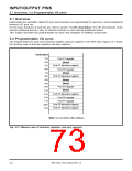
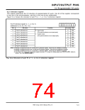
5.2.1 Direction register
This register determines the I/O direction of programmable I/O ports. One bit of this register corresponds
to one pin of the microcomputer, and this is the one-to-one relationship.
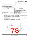
Figure 5.2.2 shows the structure of port Pi (i = 1, 2, 5 to 7) direction register.
b7 b6 b5 b4 b3 b2 b1 b0
Port Pi direction register (i = 1, 2, 5 to 7)
(Addresses 516, 816, D16, 1016, 1116)
Bit
Bit name
Function
At reset R/W
0
1
2
3
4
5
6
7
Port Pi0 direction bit
Port Pi1 direction bit
Port Pi2 direction bit
Port Pi3 direction bit
Port Pi4 direction bit
Port Pi5 direction bit
Port Pi6 direction bit
Port Pi7 direction bit
0 : Input mode
0
0
0
0
0
0
0
0
RW
RW
RW
RW
RW
RW
RW
RW
(The port functions as an input port.)
1 : Output mode
(The port functions as an output port.)
Notes 1: Nothing is assigned for bits 0 to 4 of the port P5 direction register. These bits are undefined at reading.
2: Nothing is assigned for bits 6 and 7 of the port P6 direction register. These bits are undefined at reading.
3: Nothing is assigned for bits 5 to 7 of the port P7 direction register. These bits are undefined at reading.
4: Any of bits 0 to 5 of the port P6 direction register becomes “0” by input of a falling edge to pin P6OUTCUT/INT4. (Refer to
section “5.2.3 Pin P6OUTCUT/INT4.”)
Fig. 5.2.2 Structure of port Pi (i = 1, 2, 5 to 7) direction register
7906 Group User’s Manual Rev.2.0
5-3

 RENESAS [ RENESAS TECHNOLOGY CORP ]