CLOCK GENERATING CIRCUIT
4.1 Oscillation circuit examples
4.1 Oscillation circuit examples
To the oscillation circuit, a ceramic resonator or a quartz-crystal oscillator can be connected, or the clock
which is externally generated can be input. Oscillation circuit examples are shown below.
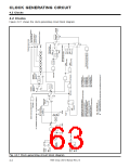
4.1.1 Connection example with resonator/oscillator
Figure 4.1.1 shows an example where pins XIN and XOUT connect across a ceramic resonator/quartz-crystal
oscillator.
The circuit constants such as Rf, Rd, CIN, and COUT (shown in “Figure 4.1.1”) depend on the resonator/
oscillator. These values shall be set to the values recommended by the resonator/oscillator manufacturer.
M37906
X
IN
X
OUT
R
f
R
d
C
IN
C
OUT
Fig. 4.1.1 Connection example of resonator/oscillator
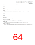
4.1.2 Externally generated clock input example
Figure 4.1.2 shows an input example of a clock which is externally generated. An external clock must be
input from pin XIN, and pin XOUT must be left open.
When an externally generated clock is input, the power source current consumption can be saved by the
stop of internal circuit’s operation between pins XIN and XOUT. (Refer to “CHAPTER 16. POWER SAVING
FUNCTION.”)
M37906
XIN
X
OUT
Open
Externally generated clock
Vcc
Vss
Fig. 4.1.2 Externally generated clock input example
7906 Group User’s Manual Rev.2.0
4-2

 RENESAS [ RENESAS TECHNOLOGY CORP ]