FLASH MEMORY VERSION
19.1 Overview
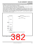
In addition to the internal flash memory area (in other words, user ROM area) shown in Figure 19.1.1, the
flash memory version has the boot ROM area of 8 Kbytes.
Figure 19.1.2 shows the memory assignment of the internal flash memory.
The user ROM area is divided into several blocks. The user ROM area is reprogrammed in the flash
memory CPU reprogramming mode, serial I/O mode, and parallel I/O mode.
The boot ROM area is assigned at addresses, overlapping with the user ROM area, however, the boot
ROM area exists in the defferent memory; the boot ROM area can be reprogrammed only in the flash
memory parallel I/O mode. (Refer to section “19.4 Flash memory parallel I/O mode.”). When being reset
with pin MD1 tied to Vcc level and pin MD0 to Vss level, the software in the boot ROM area is executed
after reset. (Refer to section “19.1.3 Boot mode.”) When pin MD1 = Vss level, however, the contents of
the boot ROM area cannot be read out.
User ROM area
Boot ROM area
(In boot mode)
(In flash memory parallel I/O mode)
16
100016
E00016
0
8 Kbytes
FFFF16
1FFF16
28 Kbytes
7FFF16
800016
16 Kbytes
8 Kbytes
BFFF16
C00016
DFFF16
E00016
8 Kbytes
(Note)
FFFF16
M37906F8
Note: Addresses FF9016 to FF9F16 are reserved for serial and parallel programmers.
Be sure not to use this area.
Fig. 19.1.2 Memory assignment of internal flash memory
7906 Group User’s Manual Rev.2.0
19-5

 RENESAS [ RENESAS TECHNOLOGY CORP ]