INPUT/OUTPUT PINS
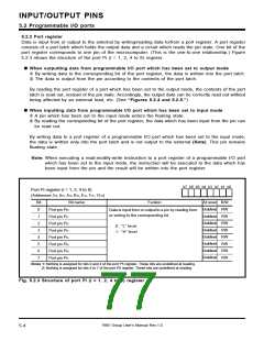
5.2 Programmable I/O ports
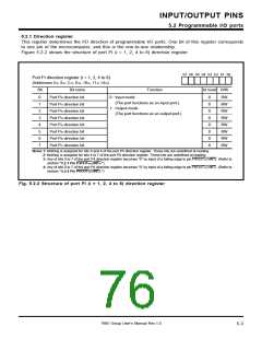
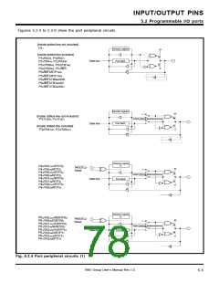
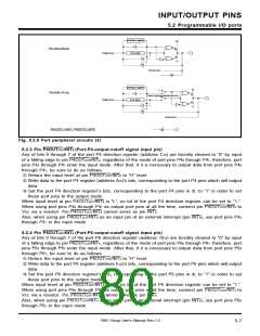
Direction register
Port latch
P82/AN10/RXD0
Data bus
Analog input
Direction register
Port latch
1
P83/AN11/TXD2
Output (internal peripheral device)
Data bus
Analog input
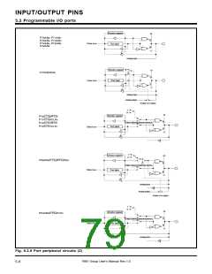
P4OUTCUT/INT0, P6OUTCUT/INT4
Fig. 5.2.6 Port peripheral circuits (3)
5.2.3 Pin P4OUTCUT/INT
Any of bits 0 through 7 of the port P4 direction register (address C16) are forcibly cleared to “0” by input
of a falling edge to pin P4OUTCUT/INT , regardless of the mode of port pins P4 through P4 ; therefore, port
pins P4 through P4 enter the input mode. After that, if it is necessary to output data from port pins P4
through P4 , be sure to do as follows:
ꢀ Return the input level at pin P4OUTCUT/INT
0
(Port-P4-output-cutoff signal input pin)
0
0
7
0
7
0
7
0
to “H” level.
ꢀ Write data to the port P4 register (address A16)’s bits, corresponding to the port P4 pins which will output
data.
ꢀ Set the port P4 direction register’s bits, corresponding to the port P4 pins in ꢀ, to “1” in order to set
these port pins to the output mode.
When input level at pin P4OUTCUT/INT
When using port pins P4 through P4
Vcc via a resistor. Pin P4OUTCUT/INT
Also, when using pin P4OUTCUT/INT as an input pin of an external interrupt (pin INT
through P4 in the input mode.
0
is “L”, no bit of the port P4 direction register can be set to “1.”
as output port pins at all the time, connect pin P4OUTCUT/INT to
cannot serve as pin INT
0
7
0
0
0
.
0
0
), use port pins P4
0
7
5.2.4 Pin P6OUTCUT/INT
Any of bits 0 through 7 of the port P6 direction register (address 1016) are forcibly cleared to “0” by input
of a falling edge to pin P6OUTCUT/INT , regardless of the mode of port pins P6 through P6 ; therefore, port
pins P6 through P6 enter the input mode. After that, if it is necessary to output data from port pins P6
through P6 , be sure to do as follows:
ꢀ Return the input level at pin P6OUTCUT/INT
4
(Port-P6-output-cutoff signal input pin)
4
0
7
0
7
0
7
4
to “H” level.
ꢀ Write data to the port P6 register (address E16)’s bits, corresponding to the port P6 pins which will output
data.
ꢀ Set the port P6 direction register’s bits, corresponding to the port P6 pins in ꢀ, to “1” in order to set
these port pins to the output mode.
When input level at pin P6OUTCUT/INT
When using port pins P6 through P6
Vcc via a resistor. Pin P6OUTCUT/INT
Also, when using pin P6OUTCUT/INT
through P6 in the input mode.
4
is “L”, no bit of the port P6 direction register can be set to “1.”
as output port pins at all the time, connect pin P6OUTCUT/INT to
cannot serve as pin INT
0
7
4
4
4
.
4
as an input pin of an external interrupt (pin INT
4
), use port pins P6
0
7
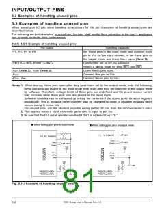
7905 Group User’s Manual Rev.1.0
5-7

 RENESAS [ RENESAS TECHNOLOGY CORP ]