SERIAL I/O
11.3 Clock synchronous serial I/O mode
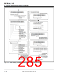
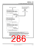
[When using interrupts] (Note 1)
[When not using interrupts]
A UARTi receive interrupt request occurs
when reception is completed.
Checking completion of reception
UART0 transmit/receive control register 1 (Address 3516
)
UART1 transmit/receive control register 1 (Address 3D16
)
UARTi receive interrupt
UART2 transmit/receive control register 1 (Address B516
)
b7
b0
1
1
Receive complete flag
0 : Reception not completed
1 : Reception completed
Reading of receive data (Note 2)
UART0 receive buffer register (Address 3616
)
UART1 receive buffer register (Address 3E16
UART2 receive buffer register (Address B616
)
)
b0
b7
Read out receive data.
Checking error
UART0 transmit/receive control register 1 (Address 3516
UART1 transmit/receive control register 1 (Address 3D16
UART2 transmit/receive control register 1 (Address B516
)
)
)
b0
b7
1
1
Overrun error flag
0 : No overrun error
1 : Overrun error detected
Processing after reading out receive data
Notes 1: When performing the processing after reception is completed, using an interrupt, be sure to
select a receive interrupt (UARTi receive interrupt mode select bit = “0.”)
2: In the case of an external clock and the RTS function selected, the RTSi output level becomes
“L” when the UARTi receive buffer register is read out. Accordingly, when performing reception
continuously, be sure to write the dummy data to the UARTi transmit buffer register before
reading out the UARTi receive buffer register.
3: This figure shows the bits and registers required for the processing.
See Figure 11.3.12 for the change of flag state and the occurrence timing of an interrupt request.
Fig. 11.3.9 Processing after reception is completed
7905 Group User’s Manual Rev.1.0
11-31

 RENESAS [ RENESAS TECHNOLOGY CORP ]