THREE-PHASE WAVEFORM MODE
10.2 Block description
10.2.8 Timer A3
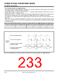
Timer A3 is used to control the carrier’s period of the whole three-phase waveform and is used in the timer
mode.
Note that a pulse is output, due to timer A3, from pin P6
(2) Pulse output function.”) When not outputing the pulse, be sure to clear bit 2 of the timer A3 mode
register (address 5916) to “0.” At this time, pin P6 can be used as a programmable I/O port pin.
6
/TA3OUT. (Refer to section “7.3.3 Select function;
6
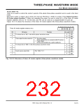
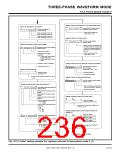
Figure 10.2.12 shows the structure of the timer A3 mode register (the three-phase waveform mode).
b7 b6 b5 b4 b3 b2 b1 b0
Timer A3 mode register (Address 5916)
0 0 0
0 0
Function
Fix these bits to “002” in the three-phase waveform mode.
Bit
0
Bit name
At reset R/W
0
0
0
RW
RW
RW
1
0 : No pulse output
Pulse output function select bit
2
(TA3OUT pin functions as a programmable I/O port pin.)
1 : Pulse output
(TA3OUT pin functions as a pulse outpt pin.)
3
4
5
6
7
0
0
RW
RW
Fix these bits to “0002” in the three-phase waveform mode.
0
0
RW
RW
See Table 7.2.3.
Count source select bits
0
RW
Fig. 10.2.12 Structure of timer A3 mode register (three-phase waveform mode)
7905 Group User’s Manual Rev.1.0
10-15

 RENESAS [ RENESAS TECHNOLOGY CORP ]