PULSE OUTPUT PORT MODE
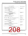
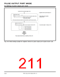
9.5 Pulse output port mode operation
9.5 Pulse output port mode operation
The operation of pulse output port 0 is described below and is also applied to the operation of pulse output port 1.
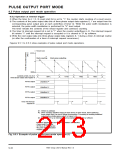
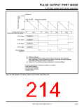
9.5.1 Pulse output trigger
(1) RTP0
The pulse output trigger can be selected from an internal trigger and an external trigger.
When the pulse output trigger select bits (bits 7, 6 at address A816) = “00 ,” an internal trigger is
,” an external trigger is selected.
0
to RTP0
3
in pulse mode 0; RTP0
0
to RTP0
3
, RTP1
0
, RTP1
1
in pulse mode 1
2
selected; when these bits = “01
2
,” “10
2
,” or “11
2
✽ Internal trigger
A trigger occurs at an underflow of timer A0. This trigger occurrence can be confirmed by using
the timer A0 interrupt request bit.
✽ External trigger
A trigger occurs at a valid edge input to pin RTPTRG0 (Note). This trigger occurrence can be confi-
rmed by using the INT
edges.
3
interrupt request bit. Table 9.5.1 lists the setting of INT according to valid
3
When using pin P5
3
/RTPTRG0 as an input pin for an external trigger, be sure to clear the port P5 direction
pin, in order to set the port P5 pin to the input mode.
register’s bit, corresponding to port P5
3
3
Note: This is set by the pulse output trigger select bits (bits 7, 6 at address A816).
Table 9.5.1 Setting of INT according to valid edges
3
Valid edge input to pin RTPTRG0
Setting of INT
Falling (edge sense)
Rising (edge sense)
Falling and Rising (edge sense): used alternately
3
(Note)
Falling
Rising
Falling and Rising
Note: Refer to section “6.10 External interrupts.”
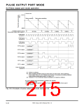
(2) RTP1
0
to RTP1
3
in pulse mode 0; RTP1
2
, RTP1 in pulse mode 1
3
The pulse output trigger is an internal trigger.
A trigger occurs at an underflow of timer A3. This trigger occurrences can be confirmed by using the
timer A3 interrupt request bit.
7905 Group User’s Manual Rev.1.0
9-31

 RENESAS [ RENESAS TECHNOLOGY CORP ]