PULSE OUTPUT PORT MODE
9.5 Pulse output port mode operation
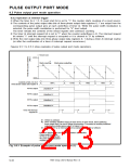
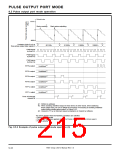
9.5.2 Operation at internal trigger
✽ When the timer Ai (i = 0, 3) count start bit is set to “1,” the counter starts counting of a count source.
✽ The contents of the pulse output data bits of three-phase output data registers 0, 1 are output from the
corresponding pulse output pins at each underflow of timer Ai. While the pulse width modulation is
selected, the pulse width modulation is performed for “H” level output.
The timer reloads the contents of the reload register and continues counting.
✽ The timer Ai interrupt request bit is set to “1” when the counter underflows in ✽. The interrupt request
bit retains “1” until the interrupt request is accepted or it is cleared to “0” by software.
✽ Write the next output data into three-phase output data registers 0, 1 during a timer Ai interrupt routine
(or after the confirmation of a timer Ai interrupt request occurrence.)
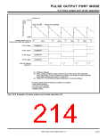
Figures 9.5.1 to 9.5.3 show examples of pulse output port mode operations.
n : Reloaded value
FFFF16
✽1
Starts counting
Starts pulse outputting
n
000016
✽1
✽1
✽1
✽1
✽1
Contents of bits 3 to 0 of
three-phase output data register 0
0011
2
0110
2
1100
2
1001
2
Undefined ✽2
RTP0
RTP0
RTP0
0
1
2
output
output
output
Undefined ✽2
Undefined ✽2
Undefined ✽2
RTP0
3
output
✽3
✽3
✽3
✽3
Timer A0 interrupt
request bit
✽1 : Written by software
✽2 : When avoiding undefined output in these terms (in other words, when stabilizing
these output level), be sure to follow the procedure “Processing of avoiding undefined
output before starting pulse output” in Figure 9.4.2.
✽3 : Cleared to “0” by an interrupt request acceptance or cleared by software.
The above applies when the following conditions are satisfied:
• Pulse mode 0 selected
• RTP00 to RTP03 selected
• No pulse width modulation
• Positive polarity
Fig. 9.5.1 Example of pulse output port mode operation (1)
7905 Group User’s Manual Rev.1.0
9-32

 RENESAS [ RENESAS TECHNOLOGY CORP ]