PULSE OUTPUT PORT MODE
9.5 Pulse output port mode operation
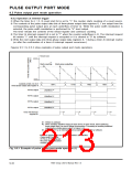
9.5.3 Operation at external trigger
✽ Each time when a valid edge of a signal input to pin RTPTRG0 (Note) is input, the contents of the pulse
output data bits of three-phase output data register 0 are output from the corresponding pulse output
pins. When the pulse width modulation is selected, the pulse width modulation is applied to “H” level
output.
✽ The INT interrupt request bit is set to “1” when a valid edge (✽) is input. (Refer to section “9.5.1 Pulse
3
output trigger.”) The interrupt request bit retains “1” until the interrupt request is accepted or it is
cleared by software.
✽ Write the next output data into three-phase output data register 0 during an INT
after the confirmation of an INT interrupt request occurrence).
3
interrupt routine (or
3
Note: This is set by the pulse output trigger select bits (bits 7, 6 at address A816).
7905 Group User’s Manual Rev.1.0
9-35

 RENESAS [ RENESAS TECHNOLOGY CORP ]