TIMER A
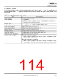
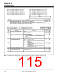
7.3 Timer mode
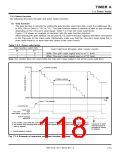
7.3.1 Setting for timer mode
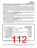
Figure 7.3.2 shows an initial setting example for registers related to the timer mode.
Note that when using interrupts, set up to enable the interrupts. For details, refer to section “CHAPTER
6. INTERRUPTS.”
Selecting timer mode and each function
b7
b0
Timer Ai mode register (i = 0 to 4) (Addresses 5616 to 5A16
)
)
0
0
0
(i = 5 to 9) (Addresses D616 to DA16
Selection of timer mode
Pulse output function select bit
0 : No pulse output
1 : Pulses output
Gate function select bits
b4 b3
0
0
0 :
1 :
No Gate function
1
1
0 : Gate function (Counter counts only while TAiIN pin’s input signal level is “L.”)
1 : Gate function (Counter counts only while TAiIN pin’s input signal level is “H.”)
Count source select bits
See Table 7.2.3.
Timer A0 register (Addresses 4716, 4616
Timer A1 register (Addresses 4916, 4816
Timer A2 register (Addresses 4B16, 4A16
Timer A3 register (Addresses 4D16, 4C16
)
)
)
Setting division ratio
(b15)
b7
(b8)
b0 b7
b0
)
Timer A4 register (Addresses 4F16, 4E16
Timer A5 register (Addresses C716, C616
Timer A6 register (Addresses C916, C816
Timer A7 register (Addresses CB16, CA16
Timer A8 register (Addresses CD16, CC16
Timer A9 register (Addresses CF16, CE16
)
)
)
)
)
)
Can be set to “000016” to “FFFF16” (n).
Note: Counter divides the count source frequency by (n + 1).
Setting interrupt priority level
Timer Ai interrupt control register
b0
(i = 0 to 4) (Addresses 7516 to 7916
b7
)
(i = 5 to 9) (Addresses F516 to F916
)
Interrupt priority level select bits
When using interrupts, set these bits to one of
levels 1 to 7.
When disabling interrupts, set these bits to
level 0.
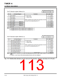
Setting count start bit to “1.”
Setting port P6, port P2, and port P4 direction registers
b7
b0
b7
b0
Count start register 0 (Address 4016
)
Port P6 direction register (Address 1016
)
Timer A0 count start bit
Timer A1 count start bit
Timer A2 count start bit
Timer A3 count start bit
Pin TA0IN
Pin TA1IN
Pin TA2IN
Pin TA3IN
b7
b0
Timer A4 count start bit
Port P2 direction register (Address 816
)
b7
b0
Pin TA4IN
Pin TA9IN
Count start register 1 (Address 4116
)
Timer A5 count start bit
Timer A6 count start bit
Timer A7 count start bit
Timer A8 count start bit
Timer A9 count start bit
b7
b0
Port P4 direction register (Address C16
)
Pin TA5IN
Pin TA6IN
Pin TA7IN
Pin TA8
N
When gate function is selected, clear the bit corresponding to the TAiIN
pin to “0.”
Count starts.
Fig. 7.3.2 Initial setting example for registers relevant to timer mode
7905 Group User’s Manual Rev.1.0
7-13

 RENESAS [ RENESAS TECHNOLOGY CORP ]