RTL8201CL
Datasheet
8.2.4. SNI Reception Cycle Timing
Table 36. SNI Reception Cycle Timing
Symbol
Description
Minimum
Typical
Maximum
Unit
ns
ns
ns
ns
ns
ns
ns
ns
t1
t2
t3
t4
t5
t6
t7
t8
RXCLK high pulse width
RXCLK low pulse width
RXCLK period
RXD0 setup to RXCLK rising edge
RXD0 hold after RXCLK rising edge
Receive frame to CRS high
End of receive frame to CRS low
Decoder acquisition time
36
36
80
40
40
120
50
160
1800
600
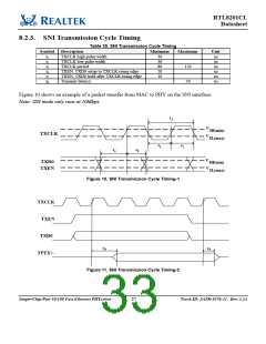
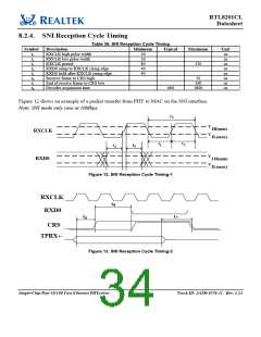
Figure 12 shows an example of a packet transfer from PHY to MAC on the SNI interface.
Note: SNI mode only runs at 10Mbps.
t3
V
IH(min)
IL(max)
RXCLK
V
t2
t1
t4
t5
V
V
RXD0
I H(min)
IL(max)
Figure 12. SNI Reception Cycle Timing-1
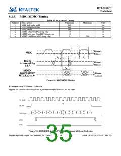
RXCLK
t8
RXD0
t6
t7
CRS
TPRX+-
Figure 13. SNI Reception Cycle Timing-2
Single-Chip/Port 10/100 Fast Ethernet PHYceiver
28
Track ID: JATR-1076-21 Rev. 1.24

 REALTEK [ Realtek Semiconductor Corp. ]