RTL8201CL
Datasheet
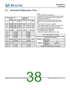
9.1. Mechanical Dimensions Notes
Notes:
1.To be determined at seating plane -c-
2.Dimensions D1 and E1 do not include mold protrusion.
D1 and E1 are maximum plastic body size dimensions
including mold mismatch.
Symbol Dimension in
inchs
Dimension in
millimeters
Min
-
Nom
-
Max
0.067
Min
-
Nom
-
Max
1.70
3.Dimension b does not include dambar protrusion.
Dambar can not be located on the lower radius of the
foot.
A
A1
A2
b
0.000 0.004
0.051 0.055
0.006 0.009
0.006 0.008
0.008
0.059
0.011
0.010
0.00
1.30
15
0.1
0.20
1.50
0.29
0.25
4.Exact shape of each corner is optional.
5.These dimensions apply to the flat section of the lead
between 0.10 mm and 0.25 mm from the lead tip.
6. A1 is defined as the distance from the seating plane to
the lowest point of the package body.
1.40
0.22
0.20
b1
0.15
c1
D
D1
E
0.004
-
0.006
0.09
-
0.16
7.Controlling dimension: millimeter.
8. Reference document: JEDEC MS-026, BBC
0.354 BSC
0.276 BSC
0.354 BSC
0.276 BSC
0.020 BSC
9.00 BSC
7.00 BSC
9.00 BSC
7.00 BSC
0.50 BSC
TITLE: 48LD LQFP (7x7x1.4mm)
PACKAGE OUTLINE DRAWING, FOOTPRINT 2.0mm
LEADFRAME MATERIAL:
E1
e
L
L1
θ
θ1
θ2
θ3
0.016 0.024
0.039 REF
3.5°
0.031
0.40
0.60
1.00 REF
3.5°
0.80
APPROVE DOC. NO.
VERSION
PAGE
1
OF
SS048 - P1
0°
0°
9°
-
0°
0°
9°
-
-
-
CHECK
DWG NO.
DATE
12° TYP
12° TYP
12° TYP
12° TYP
REALTEK SEMICONDUCTOR CORP.
Single-Chip/Port 10/100 Fast Ethernet PHYceiver
32
Track ID: JATR-1076-21 Rev. 1.24

 REALTEK [ Realtek Semiconductor Corp. ]