RTL8201CL
Datasheet
5.4. 10Mbps/100Mbps Network Interface
Table 4. 10Mbps/100Mbps Network Interface
Name
TPTX+
TPTX-
Type
O
O
Pin No.
Description
Transmit Output.
34
33
Differential transmit output pair shared by 100Base-TX, 100Base-FX and
10Base-T modes. When configured as 100Base-TX, output is an MLT-3 encoded
waveform. When configured as 100Base-FX, the output is pseudo-ECL level.
Transmit Bias Resistor Connection.
RTSET
I
28
This pin should be pulled to GND by a 2KΩ (1%) resistor to define driving
current for the transmit DAC. The resistance value may be changed, depending
on experimental results of the RTL8201CL.
TPRX+
TPRX-
I
I
31
30
Receive Input.
Differential receive input pair shared by 100Base-TX, 100Base-FX, and
10Base-T modes.
5.5. Device Configuration Interface
Table 5. Device Configuration Interface
Name
Type
Pin No.
Description
ISOLATE
I
43
Set high to isolate the RTL8201CL from the MAC. This will also isolate the MDC/MDIO
management interface. In this mode, the power consumption is minimum. This pin can be
directly connected to GND or VCC.
RPTR
I
40
39
Set high to put the RTL8201CL into repeater mode. This pincan be directly
connected to GND or VCC.
This pin is latched to input during a power on or reset condition. Set high to put
the RTL8201CL into 100Mbps operation. This pin can be directly connected to GND
or VCC.
SPEED
LI
DUPLEX
ANE
LI
LI
38
37
This pin is latched to input during a power on or reset condition. Set high to
enable full duplex. This pin can be directly connected to GND or VCC.
This pin is latched to input during a power on or reset condition. Set high to
enable Auto-negotiation mode, set low to force mode. Thispin canbedirectly
connected to GND or VCC.
LDPS
I
41
44
Set high to put the RTL8201CL into LDPS mode. Thispin canbedirectlyconnected
toGND orVCC. See7.7 Power Down, Link Down, Power Saving, and Isolation
Modes, page 20, for more information.
This pin is latched to input during a power on or reset condition. Pull high to set
the RTL8201CL into MII mode operation. Set low for SNI mode. Thispincan be
directly connected to GND or VCC.
MII/SNIB
LI/O
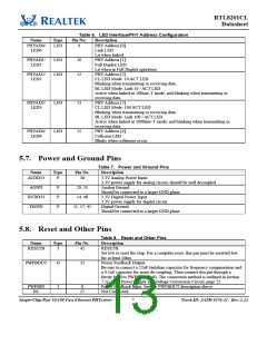
5.6. LED Interface/PHY Address Configuration
These five pins are latched into the RTL8201CL during power up reset to configure the PHY address
[0:4] used for the MII management register interface. In normal operation, after initial reset, they are used
as driving pins for status indicator LEDs. The driving polarity, active low or active high, is determined by
each latched status of the PHY address [4:0] during power-up reset. If the latched status is High, then it
will be active low. If the latched status is Low, then it will be active high. See section 7.5 LED and PHY
Address Configuration, page 19, for more information.
Single-Chip/Port 10/100 Fast Ethernet PHYceiver
6
Track ID: JATR-1076-21 Rev. 1.24

 REALTEK [ Realtek Semiconductor Corp. ]