©Quantum Research Group Ltd.
See Section 3.15, page 10, for a description of the Alert pin
which can be used to reduce communication traffic.
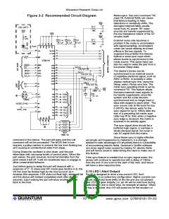
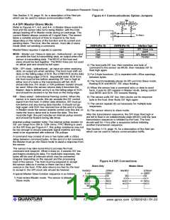
Figure 4-1 Communications Option Jumpers
Vcc
Opt A
Opt B
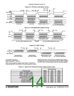
4.4 SPI Master-Slave Mode
L
H
H
L
Refer to Figures 4-1, 4-2, and 4-4. In Master-Slave mode the
host and the sensor take turns being Master, with the host
always leading off in Master mode during an exchange. The
current Master always controls all 3 signal lines. The sensor
takes a variable amount of time to respond to the host,
depending on the nature of the function and its current and
pending tasks. The host, like the sensor, must idle in slave
mode when not sending a command.
10K
10K
13
14
X0
X1
To Matrix
X0OPA (Pin 13)
X0OPB (Pin 14)
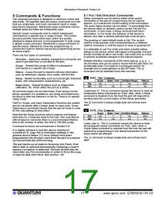
Interface Type
Low
Low
High
High
Low
High
Low
High
SPI, Slave only
UART
Master/Slave requires 3 signals to operate:
MOSI - Master out / Slave in data pin - bidirectional - an input
pin while the host is transmitting data; an output when the
sensor is transmitting data. The MOSI of the host and
slave should be tied together. The MISO lines are not used
on either part and should be left open.
SPI, Master/Slave
Parallel
2) The host pulls SS’ low, then transfers one byte of
command to the sensor via MOSI, then releases SS’ to
float high again.
SCK - SPI clock - bidirectional - an input pin when receiving
data; an output pin when sending. The host must shift out
data on the falling edge of SCK; the QT60161B clocks data
in on the rising edge of SCK. Important note: SCK from
the host must be low before asserting SS’ low or high at
either end of a byte or the transmission will fail. SCK
should idle low; if in doubt, a 10K pulldown resistor should
be used. When the sensor returns data it becomes the
Master; data is shifted out by it on the falling edge of SCK
and should be clocked in by the host on the rising edge.
3) For 2-byte functions, (2) is repeated with m50us spacings
between bytes.
4) The host immediately places its SPI port into Slave mode,
floating SCK and MOSI’; SS’ stays floating.
5) When the sensor has a command echo or data to send
back, it puts its SPI register in Master mode, taking control
over MOSI and SCK. SS' remains floating.
SS’ - Slave select - bidirectional framing control. When the
sensor is in slave mode, this pin accepts the SS’ control
signal from the host. In either data direction, SS' must go
low before and any during data transfer; it should not go
high again until SCK has returned low at the end of a byte.
In Master mode the sensor asserts control over this line, to
make the host a slave and to frame the data. This line
must idle high; the part includes an internal pullup resistor
and should be floated during idle times.
6) The sensor pulls SS’ low, then clocks out its response
byte to the host, then floats SS’ high again.
7) The sensor repeats (6) as necessary for multiple byte
responses.
8) The sensor returns to slave mode.
After the transmission sequence, the SPI lines float high or
are left to float in an indeterminate state (MOSI) until the next
transmission sequence is initiated by the host. The host
should wait for >1ms after a sequence before initiating
another transmission sequence.
Internal pullup resistor note: The internal pullup resistor on
SS’ can range from 35k to 120k ohms. If RC filtering is used
on the SPI lines per Figure 4-7, this pullup resistance may not
be low enough to ensure adequate signal risetime and may
need to be augmented with external 10k pullups.
See Section 3.15, page 10, for a description of the Alert pin
which can be used to reduce communication traffic.
A command may consist of one or two bytes with a m50us
delay between command bytes. At the end of a full command,
the Master must go into Slave mode to await a response from
the sensor.
The sensor may take some time to process the host
command and respond. When it does so, it asserts SS’ low
and begins clocking its data. For multi-byte responses, the
bytes will be sent at intervals which may be somewhat
irregular depending on the request and the processing
load of the sensor. The host must be prepared to accept
the sensor data as it comes or there can be a data
overrun in the host. If the data returns too fast for the host
to accept it, the SPI clock rate should be lowered.
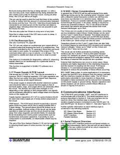
Figure 4-2 SPI Connections
Slave-Only
Master-Slave
Host MCU
QT60xx5
Host MCU
QT60xx5
DRDY
SS
P_IN
P_OUT
SCK
DRDY
SS
A typical Master-Slave function sequence is as follows:
SS
SCK
1) Host enters Master mode. The sensor is already in
Slave mode.
SCK
SCK
MISO
MOSI
SS
MISO
MOSI
MISO
MOSI
MISO
MOSI
Vdd
lQ
13
www.qprox.com QT60161B / R1.03

 QUANTUM [ QUANTUM RESEARCH GROUP ]