©Quantum Research Group Ltd.
Noise sync: See also command ^W,
page 26. External fields can cause
interference leading to false
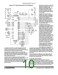
Figure 3-2 Recommended Circuit Diagram
detections or sensitivity shifts. The
strongest external fields usually
come from AC power. RF noise
sources are heavily suppressed by
the low impedance nature of the QT
circuitry itself.
External noise only becomes a
problem if the noise is uncorrelated
with signal sampling; uncorrelated
noise can cause aliasing and beat
effects in the key signals. To
suppress this problem the devices
feature a noise sync input which
allows bursts to synchronize to the
noise source. This same input can
also be used to wake the part from a
low-power Sleep state.
The device’s bursts can be
synchronized to an external source
of repetitive electrical signal, such as
50Hz or 60Hz, or possibly a video
display vertical sync line, using the
Sleep_wake / Noise sync line. The
noise sync operating mode is set by
command ^W. This feature allows
dominant external noise signals to
be heavily suppressed, since the
system and the noise become
synchronized and no longer beat or
alias with respect to each other. The
sync occurs only at the burst for key
0 (X0Y0); the device waits for the
sync signal for up to 100ms after the
end of a preceding full matrix scan
(after key #15), then when a negative
sync edge is received, the matrix is
scanned in its entirety again.
The sync signal drive should be a
buffered logic signal, or perhaps a
diode-clamped signal, but never a
raw AC signal from the mains.
Since Noise sync is highly effective
yet simple and inexpensive to implement, it is strongly
advised to take advantage of it anywhere there is a possibility
of encountering electric fields. Quantum’s QmBtn software
can show signal noise caused by nearby AC electric fields
and will hence assist in determining the need to make use of
this feature.
command to the device. The part will wake and the null
command will not be processed. The MOSI line in turn
requires a pullup resistor to prevent the line from floating low
and causing an unintentional wake from sleep.
During Sleep the oscillator is shut down, and the part
hibernates with microamp levels of current drain. When the
part wakes, the part resumes normal functionality from the
point where it left off. It will not recalibrate keys or engage in
other unwarranted behavior.
If the sync feature is enabled but no sync signal exists, the
sensor will continue to operate but with a delay of 100ms
from the end of one scan to the start of the next, and hence
will have a slow response time.
Just before going to sleep the part will respond with a
response of 'Z'. In slave-only SPI mode (see Section 4.3), the
SS line must be floated high by the host as soon as it
3.15 LED / Alert Output
receives this response; if SS does not float high, sleep will fail Pin 40 is designed to drive a low-current LED, 5mA
and the device will instead completely reset after about 2
seconds. Upon waking the part will issue another 'Z' byte
back to the host.
maximum, in an active-low configuration. Higher currents can
cause significant level shifts on the die and are not advised.
The LED will glow brightly (i.e. pin 40 will be solid low) during
calibration of one or more keys, for example at startup. When
a key is detected, the LED will pulse low for the duration of
lQ
10
www.qprox.com QT60161B / R1.03

 QUANTUM [ QUANTUM RESEARCH GROUP ]