©Quantum Research Group Ltd.
Run-time data responses, such as key detection or error
just before and during reception of data from the host. It
must not go high again until the SCK line has returned low;
during data or echo response it must not go high until after
the host has sensed that DRDY’ has gone high from the
device. This pin must idle high. The SS’ pin has an internal
pullup resistor inside.
information, requires simple single-byte functions to evoke a
response from the part.
Setup mode interactions mostly use 2-byte functions from the
host to cause the part to alter its behavior; these functions
also cause writes to the internal eeprom.
DRDY’ - Data Ready - active-low - indicates to the host that
the part is ready to send data back subsequent to a
command from the host. This pin idles high. The DRDY’
pin has an internal pullup resistor inside.
The concept of 'scope' is used to allow functions to operate
on individual keys or groupings of keys. The scope of
subsequent functions can be altered by short initial scope
instructions.
Internal pullup resistors note: The internal pullup resistors
can range from 35k to 120k ohms. If RC filtering is used on
the SPI lines per Figure 4-6, this resistance may not be low
enough to ensure adequate signal risetime and may need to
be augmented with external 10k pullups.
See Section 5 for protocol details.
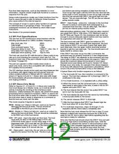
4.2 SPI Port Specifications
The part has an SPI synchronous serial interface with the
following specifications at 12MHz oscillator frequency:
The host must wait until DRDY’ goes low before an SPI
transfer to retrieve data. For multi-byte responses, the host
must observe DRDY' to see when it goes high again after
each data byte, then low again, before executing another
transfer to get the next data byte. The host should send null
bytes (0x00) to retrieve data.
Max clock rate, Fck
Data length
Host command space, Tcm
Response delay to host, Tdr1
Drdy delay from response, Tdr2
Multi-byte return spacing, Tdr3
3MHz
8 bits
m 50µs
Table 4-1, also, Sec. 6
1µs to 1ms
10µs to 2ms
If the DRDY’ line does not go low after a command, the
command was not properly received or it was inappropriate.
The delay to DRDY’ low depends on the command and how
many bytes of data are being stored into eeprom; Table 4-1
shows the maximum delays encountered in most cases.
Absolute worst case delays are found in Section 6-5; these
timings occur only rarely, for example if the device happens
to be busy with adjacent key suppression calculations, which
occurs only at the moment when a key is first detected.
The host can clock the SPI with the part in Slave mode at any
rate up to and including the maximum clock rate Fck. The
maximum clock rate of the part in Master mode is determined
by Setup ^Q (page 25).
The part can operate in either master-slave mode or
slave-only mode, and is thus compatible with virtually all
SPI-capable microcontrollers.
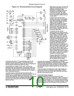
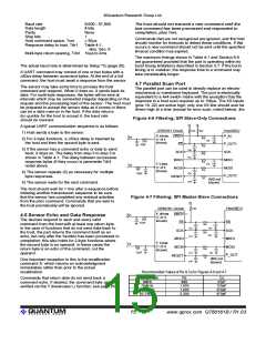
The SPI interface should not be used over long distances due
to problems with signal ringing and introduced noise etc.
unless suitably buffered or filtered with RC networks as
shown in Figures 4-6 and 4-7. Slower data rates with longer
RC timeconstants will provide enhanced resistance to noise
and ringing problems.
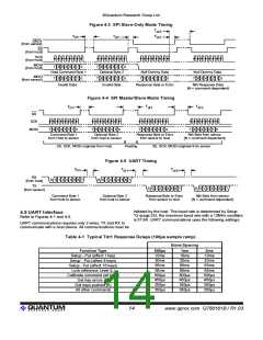
A typical Slave-only function sequence is as follows:
1) The host pulls SS’ low, then transfers a command to the
sensor. The host then releases SS’ to float high. DRDY’ is
unaffected in this step.
2) For 2-byte functions, (1) is repeated with a m50us delay.
3) When the sensor has the command echo or requested
data ready to send back to the host, it loads it into its SPI
register and pulls DRDY’ low.
4.3 SPI Slave-Only Mode
Refer to Figures 4-1, 4-3 and 4-2. In Slave-only mode the
host must always be in Master mode, as it controls all SPI
activity including the clocking of the interface in both
directions. Unlike hardware SPI slaves, the QT60161B needs
processing time to respond to functions. DRDY’ is used to let
the host know when data is ready for collection; it indicates to
the host when data is ready in response to a command so
that the host can clock over the data.
4) The host detects that the sensor has pulled DRDY’ low
and in turn the host pulls SS’ low.
5) The host obtains the byte from the sensor by transmitting
a dummy byte (0x00) to the sensor.
6) The sensor releases DRDY’ to float high.
This mode requires 5 signals to operate:
7) After the host detects that DRDY' has floated high the
host must allow SS’ to also float high.
MOSI - Master out / Slave in data pin; used as an input for
data from the host at all times. This pin should be
connected to the MOSI pin of the host device.
8) For multi-byte responses, steps (3) through (7) are
repeated until the return data is completely sent.
MISO - Master in / Slave out data pin; used as an output for
data to the host at all times. This pin should be connected
to the MISO pin of the host device.
Note that the host must release the SS’ line in step (7) even
between multiple byte responses because the QT60161B
waits for the SS’ line to return high before signalling that the
next byte is ready for collection.
SCK - SPI clock - input only clock pin from host. The host
must shift out data on the falling edge of SCK; the
QT60161B clocks data in on the rising edge of SCK.
Important note: SCK must idle low just before and after
SS’ transitions either up or down, or the transmission will
fail; between bytes SCK should idle low.
Note also that the host should check the DRDY’ line and wait
for it to go high before transmitting another byte. Until the
DRDY’ line is released the sensor is still processing a data
return, even if the complete response data has been fully
transferred; the sensor may still be busy when the host
finishes the byte transfer and may not be able to digest a new
command immediately.
SS’ - Slave select - input only; this pin acts as a framing
signal to the sensor from the host. This line must go low
lQ
12
www.qprox.com QT60161B / R1.03

 QUANTUM [ QUANTUM RESEARCH GROUP ]