©Quantum Research Group Ltd.
the burst during which the key is being sensed, i.e. with a
3.18 ESD / Noise Considerations
very low duty cycle. Each additional key being detected will
also create a low pulse for that key’s burst. During all other
times, the LED pin will be off (high).
In general the QT60161B will be well protected from static
discharge during use by the overlying panel. However, even
with a dielectric panel transients currents can still flow into
scan lines via induction or in extreme cases, dielectric
breakdown. Porous or cracked materials may allow a spark to
tunnel through the panel. In all cases, testing is required to
reveal any potential problems. The IC has diode protected
pins which can absorb and protect the device from most
induced discharges, up to 5mA.
This pin can be used to alert the host that there is key activity,
in order to further limit the amount of communication between
the device and the host. The LED / Alert line should ideally be
connected to an interrupt pin on the host that can detect a
negative edge, following which the host can proceed to poll
the device for keys.
The X lines are not usually at risk during operation, since they
are low-resistance output drives. Diode clamps can be used
on the X and Y matrix lines if desired. The diodes should be
high speed / high current types such as BAV99 dual diodes,
connected from Vdd to Vss with the diode junction connected
to the matrix pin. Diode arrays can also be used.
This line also pulls low if there is a key error of any kind.
Note that in sleep mode if the LED was on prior to sleep, it
will remain on during sleep.
3.16 Oscilloscope Sync
See also Command ^R, page 26
Capacitors placed on the X and Y matrix lines can also help
to a limited degree by absorbing ESD transients and lowering
induced voltages. Values up to 100pF on the X lines and
22pF on the Y lines can be used.
The ‘SO’ pin can output an oscilloscope sync signal which is
a positive pulse that brackets the burst of a selected key. This
feature is controlled by the ^R command. More than one burst
can output a sync pulse, for example if the scope of the
command when set is a row or column, or is all keys. The ^R
command is volatile and does not survive a reset or power
down.
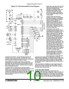
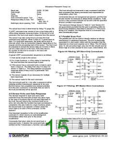
The circuit can be further protected by inserting series
resistors into the X and/or Y lines to limit peak transient
current. RC networks as shown in Figures 4-6 and 4-7 can
provide enhanced protection against ESD while also limiting
the effects of external EMI should this be a problem.
This feature is invaluable for diagnostics; without it, observing
signals clearly on an oscilloscope for a particular burst is
nearly impossible.
External field interference can occur in some cases; these
problems are highly dependent on the interfering frequency
and the manner of coupling into the circuit. PCB layout
(Section 3.17) and external wiring should be carefully
designed to reduce the probability of these effects occurring.
This function is supported in QmBtn PC software via a
checkbox.
3.17 Power Supply & PCB Layout
SPI / UART data noise: In some applications it is necessary
to have the host MCU at a distance from the sensor, perhaps
with the interface coupled via ribbon cable. The SPI link is
particularly vulnerable to noise injection on these lines;
corrupted or false commands can be induced from transients
on the power supply or ground wiring. Bypass capacitors and
series resistors can be used to prevent these effects as
shown in Figures 4-6 and 4-7.
Vdd should be 5.0 volts +/- 5%. This can be provided by a
common 78L05 3-terminal regulator. LDO type regulators are
often fine but can suffer from poor transient load response
which may cause erratic signal behavior.
If the power supply is shared with another electronic system,
care should be taken to assure that the supply is free of
low-level spikes, sags, and surges which can adversely affect
the circuit. The devices can track slow changes in Vcc
depending on the settings of drift compensation, but signals
can be adversely affected by rapid voltage steps and impulse
noise on the supply rail.
4 Communications Interfaces
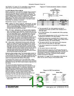
The QT60161B uses parallel, UART, and SPI interfaces to
communicate with a host MCU. The serial interfaces use a
protocol described in Section 5. Only one interface can be
used at a time; the interface type is selected by
Supply bypass capacitors of 0.1uF to a ground plane should
be used near every supply pin of every active component in
the circuit.
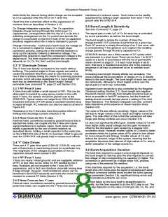
resistor-coupled jumpers connected to pins X0OPA (pin 13)
and X0OPB (pin 14) shown in Table 4-1. See also Figure 3-2.
PCB layout: The PCB layout should incorporate a ground
plane under the entire circuit; this is easily possible with a
2-layer design. The ground plane should be broken up as
little as possible. Internal nodes of the circuit can be quite
sensitive to external noise and the circuit should be kept
away from stray magnetic and electric fields, for example
those emanating from mains power components such as
transformers and power capacitors. If proximity to such
components is unavoidable, an electrostatic shield may be
required.
Further specific information on each interface type is
contained in the following sections:
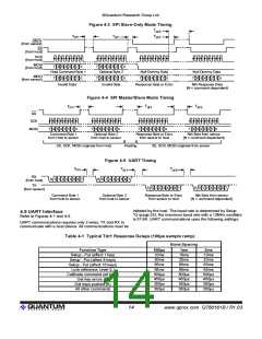
SPI Slave-Only Mode:
SPI Master-Slave Mode:
UART Interface:
Section 4.3
Section 4.4
Section 4.5
Section 4.7
Parallel Interface:
4.1 Serial Protocol Overview
The use of the Sync feature (Section 3.14) can be invaluable
in reducing these types of noise sources, but only up to a
point.
The SPI and UART interface protocols are based entirely on
polled data transmission, that is, the part will not send data to
the host of its own volition but will do so only in response to
specific commands from a host.
lQ
11
www.qprox.com QT60161B / R1.03

 QUANTUM [ QUANTUM RESEARCH GROUP ]