QS20.241, QS20.241-A1, QS20.241-C1
Q-Series
24V, 20A, SINGLE PHASE INPUT
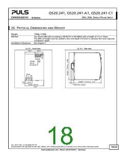
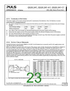
22.7. PARALLEL USE TO INCREASE OUTPUT POWER
Unit A
AC
Power supplies from the same series (Q-Series) can be paralleled to increase
the output power. The output voltage shall be adjusted to the same value
( 100mV) with the same load conditions on all units, or the units can be left
with the factory settings.
+
-
DC
+
Unit B
If more than three units are connected in parallel, a fuse or circuit breaker
with a rating of 30A or 32A is required on each output. Alternatively, a diode
or redundancy module can also be utilized.
Load
AC
+
-
-
Keep an installation clearance of 15mm (left / right) between two power
supplies and avoid installing the power supplies on top of each other. Do not
DC
use power supplies in parallel in mounting orientations other than the standard mounting orientation (input terminals
on bottom and output terminals on the top of the unit) or in any other condition where a derating of the output
current is required (e.g. altitude, above 60°C, …).
Pay attention that leakage current, EMI, inrush current, harmonics will increase when using multiple power supplies.
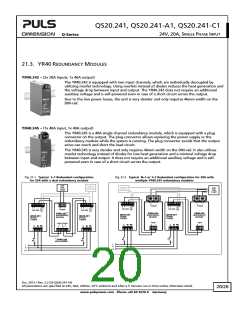
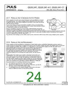
22.8. PARALLEL USE FOR REDUNDANCY
Power supplies can be paralleled for redundancy to gain higher system availability. Redundant systems require a
certain amount of extra power to support the load in case one power supply unit fails. The simplest way is to put two
power supplies in parallel. This is called a 1+1 redundancy. In case one power supply unit fails, the other one is
automatically able to support the load current without any interruption.
24V
Failure
Monitor
Redundant systems for a higher power demand are usually built in a
20A
Load
N+1 method. E.g. five power supplies, each rated for 20A are paralleled
to build a 80A redundant system. For N+1 redundancy the same
restrictions apply as for increasing the output power, see also section
22.7.
+ + - -
+
+ + - -
-
Please note: This simple way to build a redundant system does not
cover failures such as an internal short circuit in the secondary side of
the power supply. In such a case, the defective unit becomes a load for
the other power supplies and the output voltage can not be maintained
any more. This can be avoided by utilizing decoupling diodes or Mosfets,
which are included in the redundancy module YR40.241 or YR40.242.
DC-
OK
DC-
OK
Output
24V,20A
24V,20A
YR40.242*)
Redundancy
Module
QS20.241
Power
QS20.241
Power
Supply
Supply
Input Input
1
2
L
N
PE
L N PE
+
+
-
-
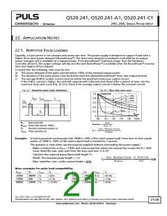
Recommendations for building redundant power systems:
a) Use separate input fuses for each power supply.
b) Monitor the individual power supply units. Therefore, use the DC-
OK relay contact of the QS20 power supply.
*) YR40.241
also possible
I
I
L
N
c)
It is desirable to set the output voltages of all units to the same
value ( 100mV) or leave it at the factory setting.
PE
Oct. 2013 / Rev. 2.2 DS-QS20.241-EN
All parameters are specified at 24V, 20A, 230Vac, 25°C ambient and after a 5 minutes run-in time unless otherwise noted.
24/26
www.pulspower.com Phone +49 89 9278 0 Germany

 PULS [ PULS GmbH ]