QS20.241, QS20.241-A1, QS20.241-C1
Q-Series
24V, 20A, SINGLE PHASE INPUT
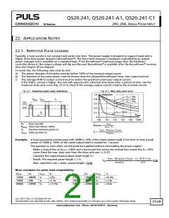
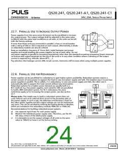
22.2. PEAK CURRENT CAPABILITY
Solenoids, contactors and pneumatic modules often have a steady state coil and a pick-up coil. The inrush current
demand of the pick-up coil is several times higher than the steady-state current and usually exceeds the nominal
output current (including the PowerBoost). The same situation applies when starting a capacitive load.
Branch circuits are often protected with circuit breakers or fuses. In case of a short or an overload in the branch circuit,
the fuse needs a certain amount of over-current to trip or to blow. The peak current capability ensures the safe
operation of subsequent circuit breakers.
Assuming the input voltage is turned on before such an event, the built-in large sized output capacitors inside the
power supply can deliver extra current. Discharging this capacitor causes a voltage dip on the output. The following
two examples show typical voltage dips:
Fig. 22-3 Peak load with 2x the nominal
Fig. 22-4 Peak load with 5x the nominal
current for 50ms, typ.
current for 5ms, typ.
24V
Output
Voltage
Output
Voltage
24V
100A
40A
20V
16V
Output
Current
Output
Current
0A
0A
10ms/DIV
1ms/DIV
Peak load 40A (resistive) for 50ms
Output voltage dips from 24V to 20V.
Peak load 100A (resistive) for 5ms
Output voltage dips from 24V to 16V.
Please note: The DC-OK relay triggers when the voltage dips more than 10% for longer than 1ms.
22.3. BACK-FEEDING LOADS
Loads such as decelerating motors and inductors can feed voltage back to the power supply. This feature is also called
return voltage immunity or resistance against Back- E.M.F. (Electro Magnetic Force).
This power supply is resistant and does not show malfunctioning when a load feeds back voltage to the power supply.
It does not matter whether the power supply is on or off.
The maximum allowed feed-back-voltage is 34Vdc. The absorbing energy can be calculated according to the built-in
large sized output capacitor which is specified in chapter 6.
22.4. EXTERNAL INPUT PROTECTION
The unit is tested and approved for branch circuits up to 20A. An external protection is only required if the supplying
branch has an ampacity greater than this. Check also local codes and local requirements. In some countries local
regulations might apply.
If an external fuse is necessary or utilized, minimum requirements need to be considered to avoid nuisance tripping of
the circuit breaker. A minimum value of 10A B- or C-Characteristic breaker should be used
Oct. 2013 / Rev. 2.2 DS-QS20.241-EN
All parameters are specified at 24V, 20A, 230Vac, 25°C ambient and after a 5 minutes run-in time unless otherwise noted.
22/26
www.pulspower.com Phone +49 89 9278 0 Germany

 PULS [ PULS GmbH ]