TOP242-249
Conditions
(Unless Otherwise Specified)
See Figure 53
Parameter
Symbol
Min
Typ
Max
Units
SOURCE = 0 V; TJ = -40 to 125 °C
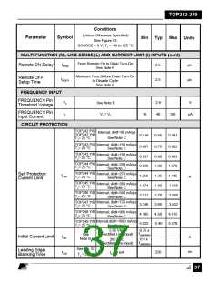
MULTI-FUNCTION (M), LINE-SENSE (L) AND CURRENT LIMIT (I) INPUTS (cont)
From Remote On to Drain Turn-On
tR(ON)
Remote ON Delay
2.5
µs
µs
See Note B
Minimum Time Before Drain Turn-On
to Disable Cycle
Remote OFF
Setup Time
tR(OFF)
2.5
See Note B
FREQUENCY INPUT
FREQUENCY Pin
Threshold Voltage
VF
IF
2.9
40
V
See Note B
VF = VC
FREQUENCY Pin
Input Current
10
100
µA
CIRCUIT PROTECTION
TOP242 P/G
Internal; di/dt=90 mA/µs
TOP242 Y/R
0.418
0.697
0.45
0.75
0.481
0.802
See Note C
TJ= 25 °C
TOP243 P/G Internal; di/dt=150 mA/µs
TJ= 25 °C
See Note C
TOP243 Y/R
Internal; di/dt=180 mA/µs
0.837
0.930
0.90
1.00
0.963
1.070
TJ= 25 °C
See Note C
TOP244 P/G
TJ= 25 °C
Internal; di/dt=200 mA/µs
See Note C
TOP244 Y/R
Internal; di/dt=270 mA/µs
Self Protection
Current Limit
ILIMIT
1.256
1.674
2.511
3.348
4.185
5.022
1.35
1.80
2.70
3.60
4.50
5.40
1.445
1.926
2.889
3.852
4.815
5.778
A
TJ= 25 °C
See Note C
TOP245 Y/R
TJ= 25 °C
Internal; di/dt=360 mA/µs
See Note C
Internal; di/dt=540 mA/µs
See Note C
TOP246 Y/R
TJ= 25 °C
Internal; di/dt=720 mA/µs
TOP247 Y/R
TJ= 25 °C
See Note C
TOP248 Y/R
TJ= 25 °C
Internal; di/dt=900 mA/µs
See Note C
Internal;di/dt=1080 mA/µs
TOP249 Y/R
TJ= 25 °C
See Note C
0.75 x
ILIMIT(MIN)
≤ 85 VAC
(Rectified Line Input)
See
Note B
Initial Current Limit
IINIT
A
0.6 x
ILIMIT(MIN)
265 VAC
(Rectified Line Input)
See Fig. 52
Leading Edge
Blanking Time
ns
tLEB
220
IC = 4 mA
TJ = 25 °C
E
7/01
August 8, 2000
37

 POWERINT [ Power Integrations ]