TOP242-250
Processor Controlled Supply Turn On/Off
parking the print heads in the storage position. In the case of
productswithadiskdrive,theshutdownproceduremayinclude
savingdataorsettingstothedisk. Aftertheshutdownprocedure
is complete, when it is safe to turn off the power supply, the
microprocessor releases the M pin by turning the optocoupler
U4 off. If the manual switch and the optocouplers U3 and U4
are not locatedclose tothe M pin, a capacitorCM maybe needed
to prevent noise coupling to the pin when it is open.
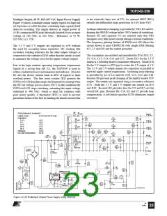
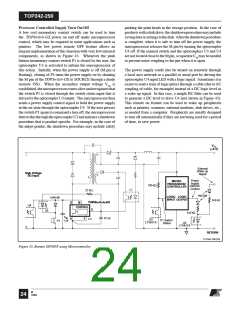
A low cost momentary contact switch can be used to turn
the TOPSwitch-GX power on and off under microprocessor
control, which may be required in some applications such as
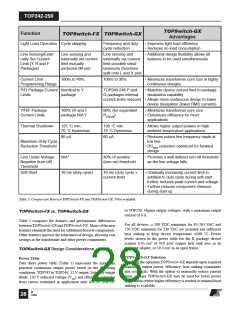
printers. The low power remote OFF feature allows an
elegant implementation of this function with very few external
components, as shown in Figure 45. Whenever the push
button momentary contact switch P1 is closed by the user, the
optocoupler U3 is activated to inform the microprocessor of
this action. Initially, when the power supply is off (M pin is
floating), closing of P1 turns the power supply on by shorting
the M pin of the TOPSwitch-GX to SOURCE through a diode
(remote ON). When the secondary output voltage VCC is
established,themicroprocessorcomesaliveandrecognizesthat
the switch P1 is closed through the switch status input that is
driven by the optocoupler U3 output. The microprocessor then
sends a power supply control signal to hold the power supply
in the on-state through the optocoupler U4. If the user presses
the switch P1 again to command a turn off, the microprocessor
detectsthisthroughtheoptocouplerU3andinitiatesashutdown
procedure that is product specific. For example, in the case of
the inkjet printer, the shutdown procedure may include safely
The power supply could also be turned on remotely through
a local area network or a parallel or serial port by driving the
optocoupler U4 input LED with a logic signal. Sometimes it is
easier to send a train of logic pulses through a cable (due toAC
coupling of cable, for example) instead of a DC logic level as
a wake up signal. In this case, a simple RC filter can be used
to generate a DC level to drive U4 (not shown in Figure 45).
This remote on feature can be used to wake up peripherals
such as printers, scanners, external modems, disk drives, etc.,
as needed from a computer. Peripherals are usually designed
to turn off automatically if they are not being used for a period
of time, to save power.
VCC
(+5 V)
+
External
Wake-up
Signal
High Voltage
DC Input
Power
Supply
ON/OFF
Control
MICRO-
PROCESSOR/
CONTROLLER
100 kΩ
U2
27 kΩ
1N4148
LOGIC LOGIC
INPUT OUTPUT
1N4148
6.8 kΩ
TOPSwitch-GX
D
S
M
U4
CONTROL
C
U3
6.8 kΩ
CM
1 nF
47 µF
F
U1
U3
LTV817A
P1 Switch
Status
P1
U4
LTV817A
RETURN
PI-2561-081204
Figure 45. Remote ON/OFF using Microcontroller.
M
24 12/04

 POWERINT [ Power Integrations ]