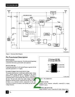
TNY264/266-268
200
100
V
V
DC-INPUT
EN
0
CLOCK
10
V
D
5
0
MAX
BYPASS
400
200
0
I
DRAIN
V
DRAIN
1
2
0
Time (ms)
V
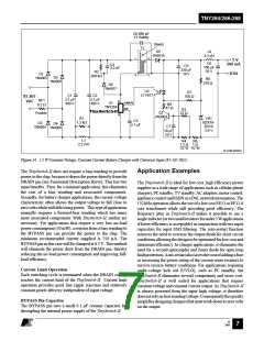
Figure 11. TinySwitch-II Power-up without Optional External UV
Resistor Connected to EN/UV Pin.
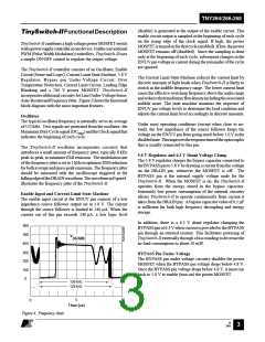
DRAIN
PI-2661-072400
200
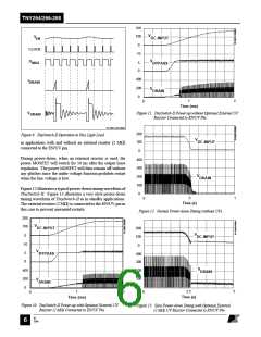
Figure 9. TinySwitch-II Operation at Very Light Load.
V
100
0
DC-INPUT
in applications with and without an external resistor (2 MΩ)
connected to the EN/UV pin.
During power-down, when an external resistor is used, the
power MOSFET will switch for 50 ms after the output loses
regulation. The power MOSFET will then remain off without
any glitches since the under-voltage function prohibits restart
when the line voltage is low.
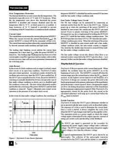
400
300
V
200
100
0
DRAIN
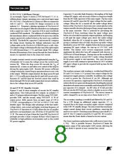
Figure 12 illustrates a typical power-down timing waveform of
TinySwitch-II. Figure 13 illustrates a very slow power-down
timing waveform of TinySwitch-II as in standby applications.
The external resistor (2 MΩ) is connected to the EN/UV pin in
this case to prevent unwanted restarts.
.5
1
0
Time (s)
Figure 12. Normal Power-down Timing (without UV).
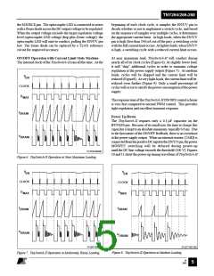
200
V
100
0
DC-INPUT
200
V
100
0
DC-INPUT
10
V
5
0
BYPASS
400
300
V
400
200
0
200
100
0
DRAIN
V
DRAIN
2.5
Time (s)
5
1
2
0
0
Time (ms)
Figure 10. TinySwitch-II Power-up with Optional External UV
Figure 13. Slow Power-down Timing with Optional External
Resistor (2 MΩ) Connected to EN/UV Pin.
(2 MΩ) UV Resistor Connected to EN/UV Pin.
B
7/01
6

 POWERINT [ Power Integrations ]