TNY253/254/255
circuitꢀisꢀsampledꢀatꢀtheꢀrisingꢀedgeꢀofꢀtheꢀoscillatorꢀClockꢀ
signalꢀ(atꢀtheꢀbeginningꢀofꢀeachꢀcycle).ꢀꢀIfꢀitꢀisꢀhigh,ꢀthenꢀtheꢀ
powerꢀMOSFETꢀisꢀturnedꢀonꢀ(enabled)ꢀforꢀthatꢀcycle,ꢀotherwiseꢀ
theꢀpowerꢀMOSFETꢀremainsꢀinꢀtheꢀoffꢀstateꢀ(cycleꢀskipped).ꢀ
Sinceꢀtheꢀsamplingꢀisꢀdoneꢀonlyꢀonceꢀatꢀtheꢀbeginningꢀofꢀeachꢀ
cycle,ꢀanyꢀsubsequentꢀchangesꢀatꢀtheꢀENABLEꢀpinꢀduringꢀtheꢀ
cycleꢀareꢀignored.ꢀ
areꢀconstant,ꢀtheꢀpowerꢀdeliveredꢀisꢀproportionalꢀtoꢀtheꢀprimaryꢀ
inductanceꢀofꢀtheꢀtransformerꢀandꢀisꢀrelativelyꢀindependentꢀofꢀ
theꢀinputꢀvoltage.ꢀꢀTherefore,ꢀtheꢀdesignꢀofꢀtheꢀpowerꢀsupplyꢀ
involvesꢀcalculatingꢀtheꢀprimaryꢀinductanceꢀofꢀtheꢀtransformerꢀ
forꢀtheꢀmaximumꢀpowerꢀrequired.ꢀꢀAsꢀlongꢀasꢀtheꢀTinySwitchꢀ
deviceꢀchosenꢀisꢀratedꢀforꢀtheꢀpowerꢀlevelꢀatꢀtheꢀlowestꢀinputꢀ
voltage,ꢀtheꢀcalculatedꢀinductanceꢀwillꢀrampꢀupꢀtheꢀcurrentꢀtoꢀ
theꢀcurrentꢀlimitꢀbeforeꢀtheꢀDCMAXꢀlimitꢀisꢀreached.
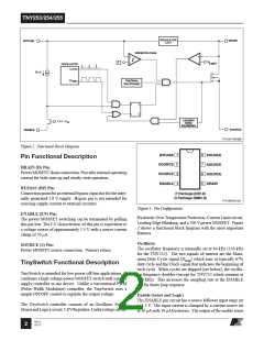
5.8 V Regulator
Theꢀ5.8ꢀVꢀregulatorꢀchargesꢀtheꢀbypassꢀcapacitorꢀconnectedꢀtoꢀ
theꢀBYPASSꢀpinꢀtoꢀ5.8ꢀVꢀbyꢀdrawingꢀaꢀcurrentꢀfromꢀtheꢀvoltageꢀ
onꢀtheꢀDRAIN,ꢀwheneverꢀtheꢀMOSFETꢀisꢀoff.ꢀꢀTheꢀBYPASSꢀpinꢀ
isꢀtheꢀinternalꢀsupplyꢀvoltageꢀnodeꢀforꢀtheꢀTinySwitch.ꢀꢀWhenꢀ
theꢀMOSFETꢀisꢀon,ꢀtheꢀTinySwitchꢀrunsꢀoffꢀofꢀtheꢀenergyꢀstoredꢀ
inꢀtheꢀbypassꢀcapacitor.ꢀExtremelyꢀlowꢀpowerꢀconsumptionꢀofꢀ
theꢀinternalꢀcircuitryꢀallowsꢀtheꢀTinySwitchꢀtoꢀoperateꢀcontinu-
ouslyꢀfromꢀtheꢀcurrentꢀdrawnꢀfromꢀtheꢀDRAINꢀpin.ꢀꢀAꢀbypassꢀ
capacitorꢀvalueꢀofꢀ0.1ꢀµFꢀisꢀsufficientꢀforꢀbothꢀhighꢀfrequencyꢀ
de-couplingꢀandꢀenergyꢀstorage.
Enable Function
TheꢀTinySwitchꢀsensesꢀtheꢀENABLEꢀpinꢀtoꢀdetermineꢀwhetherꢀ
orꢀnotꢀtoꢀproceedꢀwithꢀtheꢀnextꢀswitchꢀcycleꢀasꢀdescribedꢀearlier.ꢀ
OnceꢀaꢀcycleꢀisꢀstartedꢀTinySwitchꢀalwaysꢀcompletesꢀtheꢀcycleꢀ
(evenꢀwhenꢀtheꢀENABLEꢀpinꢀchangesꢀstateꢀhalfꢀwayꢀthroughꢀtheꢀ
cycle).ꢀꢀThisꢀoperationꢀresultsꢀinꢀaꢀpowerꢀsupplyꢀwhoseꢀoutputꢀ
voltageꢀrippleꢀisꢀdeterminedꢀbyꢀtheꢀoutputꢀcapacitor,ꢀamountꢀofꢀ
energyꢀperꢀswitchꢀcycleꢀandꢀtheꢀdelayꢀofꢀtheꢀENABLEꢀfeedback.
TheꢀENABLEꢀsignalꢀisꢀgeneratedꢀonꢀtheꢀsecondaryꢀbyꢀcomparingꢀ
theꢀpowerꢀsupplyꢀoutputꢀvoltageꢀwithꢀaꢀreferenceꢀvoltage.ꢀꢀTheꢀ
ENABLEꢀsignalꢀisꢀhighꢀwhenꢀtheꢀpowerꢀsupplyꢀoutputꢀvoltageꢀ
isꢀlessꢀthanꢀtheꢀreferenceꢀvoltage.ꢀꢀ
Undervoltage
TheꢀundervoltageꢀcircuitryꢀdisablesꢀtheꢀpowerꢀMOSFETꢀwhenꢀ
theꢀBYPASSꢀpinꢀvoltageꢀdropsꢀbelowꢀ5.1ꢀV.ꢀꢀOnceꢀtheꢀBYPASSꢀ
pinꢀvoltageꢀdropsꢀbelowꢀ5.1ꢀV,ꢀitꢀhasꢀtoꢀriseꢀbackꢀtoꢀ5.8ꢀVꢀtoꢀ
enableꢀ(turn-on)ꢀtheꢀpowerꢀMOSFET.
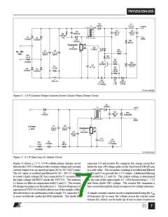
Inꢀaꢀtypicalꢀimplementation,ꢀtheꢀENABLEꢀpinꢀisꢀdrivenꢀbyꢀ
anꢀoptocoupler.ꢀꢀTheꢀcollectorꢀofꢀtheꢀoptocouplerꢀtransistorꢀisꢀ
connectedꢀtoꢀtheꢀENABLEꢀpinꢀandꢀtheꢀemitterꢀisꢀconnectedꢀtoꢀ
theꢀSOURCEꢀpin.ꢀꢀTheꢀoptocouplerꢀLEDꢀisꢀconnectedꢀinꢀseriesꢀ
withꢀaꢀZenerꢀacrossꢀtheꢀDCꢀoutputꢀvoltageꢀtoꢀbeꢀregulated.ꢀ
Whenꢀtheꢀoutputꢀvoltageꢀexceedsꢀtheꢀtargetꢀregulationꢀvoltageꢀ
levelꢀ(optocouplerꢀdiodeꢀvoltageꢀdropꢀplusꢀZenerꢀvoltage),ꢀtheꢀ
optocouplerꢀdiodeꢀwillꢀstartꢀtoꢀconduct,ꢀpullingꢀtheꢀENABLEꢀ
pinꢀlow.ꢀꢀTheꢀZenerꢀcouldꢀbeꢀreplacedꢀbyꢀaꢀTL431ꢀdeviceꢀforꢀ
improvedꢀaccuracy.ꢀꢀ
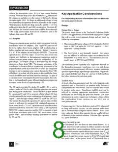
Hysteretic Over Temperature Protection
Theꢀthermalꢀshutdownꢀcircuitryꢀsensesꢀtheꢀdieꢀjunctionꢀtem-
perature.ꢀꢀTheꢀthresholdꢀisꢀsetꢀatꢀ135ꢀ°Cꢀwithꢀ70ꢀ°Cꢀhysteresis.ꢀ
Whenꢀ theꢀ junctionꢀ temperatureꢀ risesꢀ aboveꢀ thisꢀ thresholdꢀ
(135ꢀ°C)ꢀtheꢀpowerꢀMOSFETꢀisꢀdisabledꢀandꢀremainsꢀdisabledꢀ
untilꢀtheꢀdieꢀjunctionꢀtemperatureꢀfallsꢀbyꢀ70ꢀ°C,ꢀatꢀwhichꢀpointꢀ
itꢀisꢀre-enabled.ꢀ
Current Limit
TheꢀENABLEꢀpinꢀpull-downꢀcurrentꢀthresholdꢀisꢀnominallyꢀ
50ꢀµA,ꢀbutꢀisꢀsetꢀtoꢀ40ꢀµAꢀtheꢀinstantꢀtheꢀthresholdꢀisꢀexceeded.ꢀ
Thisꢀisꢀresetꢀtoꢀ50ꢀµAꢀwhenꢀtheꢀENABLEꢀpull-downꢀcurrentꢀ
dropsꢀbelowꢀtheꢀcurrentꢀthresholdꢀofꢀ40ꢀµA.
Theꢀ currentꢀ limitꢀ circuitꢀ sensesꢀ theꢀ currentꢀ inꢀ theꢀ powerꢀ
MOSFET.ꢀꢀWhenꢀthisꢀcurrentꢀexceedsꢀtheꢀinternalꢀthresholdꢀ
(ILIMIT),ꢀtheꢀpowerꢀMOSFETꢀisꢀturnedꢀoffꢀforꢀtheꢀremainderꢀofꢀ
thatꢀcycle.
ON/OFF Control
Theꢀleadingꢀedgeꢀblankingꢀcircuitꢀinhibitsꢀtheꢀcurrentꢀlimitꢀ
comparatorꢀforꢀaꢀshortꢀtimeꢀ(tLEB)ꢀafterꢀtheꢀpowerꢀMOSFETꢀ
isꢀturnedꢀon.ꢀꢀThisꢀleadingꢀedgeꢀblankingꢀtimeꢀhasꢀbeenꢀsetꢀsoꢀ
thatꢀcurrentꢀspikesꢀcausedꢀbyꢀprimary-sideꢀcapacitanceꢀandꢀ
secondary-sideꢀrectifierꢀreverseꢀrecoveryꢀtimeꢀwillꢀnotꢀcauseꢀ
prematureꢀterminationꢀofꢀtheꢀswitchingꢀpulse.
TheꢀinternalꢀclockꢀofꢀtheꢀTinySwitchꢀrunsꢀallꢀtheꢀtime.ꢀꢀAtꢀtheꢀ
beginningꢀ ofꢀ eachꢀ clockꢀ cycleꢀ theꢀ TinySwitchꢀ samplesꢀ theꢀ
ENABLEꢀpinꢀtoꢀdecideꢀwhetherꢀorꢀnotꢀtoꢀimplementꢀaꢀswitchꢀ
cycle.ꢀꢀIfꢀtheꢀENABLEꢀpinꢀisꢀhighꢀ(<ꢀ40ꢀµA),ꢀthenꢀaꢀswitchingꢀ
cycleꢀtakesꢀplace.ꢀꢀIfꢀtheꢀENABLEꢀpinꢀisꢀlowꢀ(greaterꢀthanꢀ
50ꢀµA)ꢀthenꢀnoꢀswitchingꢀcycleꢀoccurs,ꢀandꢀtheꢀENABLEꢀpinꢀ
statusꢀisꢀsampledꢀagainꢀatꢀtheꢀstartꢀofꢀtheꢀsubsequentꢀclockꢀcycle.
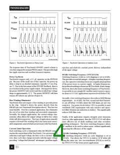
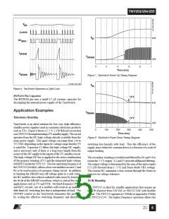
TinySwitch Operation
AtꢀfullꢀloadꢀTinySwitchꢀwillꢀconductꢀduringꢀtheꢀmajorityꢀofꢀ
itsꢀclockꢀcyclesꢀ(Figureꢀ4).ꢀꢀAtꢀloadsꢀlessꢀthanꢀfullꢀload,ꢀtheꢀ
TinySwitchꢀwillꢀ“skip”ꢀmoreꢀcyclesꢀinꢀorderꢀtoꢀmaintainꢀvolt-
ageꢀregulationꢀatꢀtheꢀsecondaryꢀoutputꢀ(Figureꢀ5).ꢀꢀAtꢀlightꢀ
loadꢀorꢀnoꢀload,ꢀalmostꢀallꢀcyclesꢀwillꢀbeꢀskippedꢀ(Figureꢀ6).ꢀ
Aꢀsmallꢀpercentageꢀofꢀcyclesꢀwillꢀconductꢀtoꢀsupportꢀtheꢀpowerꢀ
consumptionꢀofꢀtheꢀpowerꢀsupply.
TinySwitchꢀisꢀintendedꢀtoꢀoperateꢀinꢀtheꢀcurrentꢀlimitꢀmode.ꢀ
Whenꢀenabled,ꢀtheꢀoscillatorꢀturnsꢀtheꢀpowerꢀMOSFETꢀonꢀatꢀtheꢀ
beginningꢀofꢀeachꢀcycle.ꢀꢀTheꢀMOSFETꢀisꢀturnedꢀoffꢀwhenꢀtheꢀ
currentꢀrampsꢀupꢀtoꢀtheꢀcurrentꢀlimit.ꢀꢀTheꢀmaximumꢀon-timeꢀ
ofꢀtheꢀMOSFETꢀisꢀlimitedꢀtoꢀDCMAXꢀbyꢀtheꢀoscillator.ꢀꢀSinceꢀ
theꢀcurrentꢀlimitꢀandꢀfrequencyꢀofꢀaꢀgivenꢀTinySwitchꢀdeviceꢀ
Rev E
02/12
3

 POWERINT [ Power Integrations ]