The programming data (DPM and POL setup registers and the user memory) can be preloaded into DPMs by Power-
One or the DPMs can be programmed by the user via the GUI, I2C bus, or JTAG programming interface. The
DPMs can be programmed either before or after installation on a host board.
To modify POL converter settings, the user can directly access the registers of a POL converter via the I2C bus,
bypassing DPM’s POL setup registers. The I2C commands are translated by the DPM and converted into appropriate
SD commands to read / write from / into the registers of a POL converter. Writing into these registers is limited by
the hardware (LCK_N) and/or software write protections. Since POL converters do not have non-volatile memory,
data written directly into POL converter registers will be lost when the input voltage is removed.
10.4
Monitoring
10.4.1 POL Monitoring
dPwerTM and Z-one™ POL converters continuously monitor their own performance parameters such as output
voltage, output current, and temperature. The monitored parameters are stored locally in the POL converters and
updated every 1ms. If monitoring feature is enabled, the DPM will be continuously copying status and parametric data
from POL converters into DPM’s monitoring data registers.
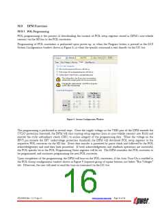
The monitoring is enabled by checking the appropriate Retrieve Monitoring bits in the GUI Group Configuration
window shown in Figure 9 or directly via the I2C bus by specific commands.
If the status monitoring is enabled, the status of each protection (overcurrent, overvoltage, etc.) is being reported. If
the parametric monitoring is enabled, then real-time values of voltage, current, and temperature are being reported.
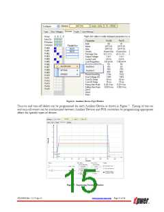
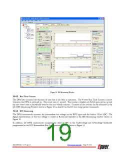
Status and parametric monitoring data of a single POL converter and groups of POL converters can be examined in
the GUI IBS Monitoring Window shown in Figure 10 or directly via the I2C bus using specific commands. Status
data for each group of POL converters is presented in the Group Status block in the left top corner of the window.
Parametric data for individual POL converters is shown in Voltage [V], Current [A], and Temp [T] screens.
DPMs also monitor and report programming status of each POL converter and results of CRC operations.
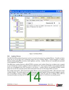
10.4.2 Monitoring of Auxiliary Devices
The DPM can read status information of the Auxiliary Devices via the PG0…PG3 inputs. The PG0…PG3 are digital
3.3V compliant inputs with internal pull-up resistors. Logic high input on a PGX pin should correspond to normal
operation of an Auxiliary Device.
Status monitoring data of Auxiliary Devices is stored in the DPM and displayed in the IBS Monitoring Window shown
in Figure 10.
ZD-00896 Rev. 5.2, 9-Apr-13
www.power-one.com Page 18 of 36

 POWER-ONE [ POWER-ONE ]