Status registers and save the content of the Run Time Counter into the non-volatile memory. The IBV Low bit in the
IBS Monitoring Window will change to red. When the IBV recovers above the IBL threshold plus the hysteresis, the
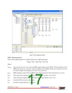
DPM will first program all POL converters and then turn them on, if the Auto Turn-On is enabled in the POL Group
configuration window shown in Figure 9. Otherwise, the user will need to send the turn-on command via the I2C bus.
When the IBV exceeds the IBH threshold plus the hysteresis, the DPM will pull OK lines low turning off all POL
converters. The POL converters will execute regular turn-off ramping their output voltages down according to the
turn-off delay and falling slew rate settings. In addition, the DPM will save the contents of the Run Time Counter into
the non-volatile memory. If the IBV does not decrease below the IBH threshold minus the hysteresis within the next
50ms, the DPM will pull low the FE_EN output and clear all bits in the POL Programming Status registers. The IBV
High bit in the IBS Monitoring Window will change to red. If the IBV still does not change, in 50ms the DPM will
pull the CB pin high for 1ms to trigger an optional crowbar protection.
One second after the IBV decreases below the IBH threshold minus the hysteresis, the DPM will pull the FE_EN
high and program all POL converters. Upon completion of the programming process, the DPM will turn on the POL
converters, if the Auto Turn-On is enabled in the POL Group configuration window shown in Figure 9.
The propagation delay between the IBV increasing/decreasing above/below corresponding thresholds and the DPM
pulling down OK lines and triggering the turn-off process is approximately 1ms.
10.4.4.1 Voltage Reference
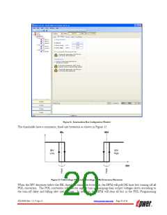
For the purposes of IBV monitoring the user can select either the DPM’s internal voltage reference or an external
2.5V voltage reference. The selection is made by clicking an appropriate radio button in the DPM Configuration/Bus
Voltages dialog as shown previously in Figure 11
.
he DPM’s internal 2.56V voltage reference guarantees 10% overall accuracy of the IBV protection thresholds. If the
accuracy is sufficient, the user does not need to make any changes to the schematic shown in Figure 3. If higher
accuracy of the IBV monitoring is desired, then a 2.5V external reference can be added as shown in Figure 13. The
GUI automatically changes values of the IBL and IBH thresholds when the reference selection is changed.
Note: If the Reference Voltage setting is changed during operation of the DPM, then the power to the DPM needs to be cycled
or the HRES_N pin needs to be pulled low and released
Figure 13. External Voltage Reference Connections
U1 and R1 are additional components. U1 is an industry standard 2.5V voltage reference such as TL431 or similar.
C1 is an existing component but its value changes depending on the type of voltage reference. Common voltage
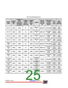
reference part numbers and values of associated components are shown in Table 4.
ZD-00896 Rev. 5.2, 9-Apr-13
www.power-one.com Page 21 of 36

 POWER-ONE [ POWER-ONE ]