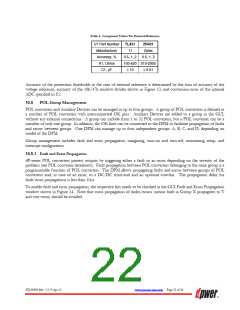
Table 4. Component Values For External Reference
TL431
TI
ZR431
Zetex
U1 Part Number
Manufacturer
Accuracy, %
R1, Ohms
0.5, 1, 2
0.5, 1, 2
100-620 510-2000
≥ 10 ≥ 0.01
C1, µF
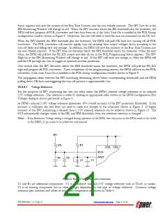
Accuracy of the protection thresholds in the case of external reference is determined by the sum of accuracy of the
voltage reference, accuracy of the 10k/47k resistive divider shown in Figure 13, and conversion error of the internal
ADC specified in 8.2.
10.5
POL Group Management
POL converters and Auxiliary Devices can be arranged in up to four groups. A group of POL converters is defined as
a number of POL converters with interconnected OK pins. Auxiliary Devices are added to a group in the GUI,
without any external connections. A group can include from 1 to 32 POL converters, but a POL converter can be a
member of only one group. In addition, the OK lines can be connected to the DPM to facilitate propagation of faults
and errors between groups. One DPM can manage up to four independent groups: A, B, C, and D, depending on
model of the DPM.
Group management includes fault and error propagation, margining, turn-on and turn-off, monitoring setup, and
interrupt configuration.
10.5.1 Fault and Error Propagation
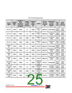
dP-series POL converters protect outputs by triggering either a fault or an error depending on the severity of the
problem (see POL converter datasheets). Fault propagation between POL converters belonging to the same group is a
programmable function of POL converters. The DPM allows propagating faults and errors between groups of POL
converters and, in case of an error, to a DC/DC front-end and an optional crowbar. The propagation delay for
fault/error propagations is less than 10µs.
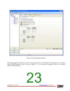
To enable fault and error propagation, the respective bits needs to be checked in the GUI Fault and Error Propagation
window shown in Figure 14. Note that cross propagation of faults/errors (means fault in Group X propagates to Y
and vice versa) should be avoided.
ZD-00896 Rev. 5.2, 9-Apr-13
www.power-one.com Page 22 of 36

 POWER-ONE [ POWER-ONE ]