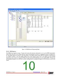
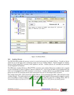
Figure 5. User Memory Window
10.2
Auxiliary Devices
The DM7300 DPM includes all necessary circuitry to control and monitor four Auxiliary Devices. Virtually any device
which has an on/off input and a monitoring output can be an Auxiliary Device. Typical examples of Auxiliary
Devices include analog POL converters, linear regulators, and fans. Auxiliary Devices are controlled and monitored
via the Graphical User Interface.
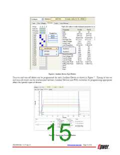
The DPM treats Auxiliary Devices as dPwer™ POL converters: each Auxiliary Device has an address and is assigned
to one of the groups as shown in Figure 8 (device at addresses 03). Turn-on and off delays can be programmed, and
faults can be propagated from POL converters to the devices. Auxiliary Devices are controlled through standard
group turn-on and off commands and are fully synchronized with turn-on/off timing of POL converters.
Four enable outputs EN0…EN3 control the Auxiliary Devices. Four monitoring inputs PG0…PG3 read status of the
Auxiliary Devices. The enable outputs and monitoring inputs are paired together and permanently assigned to specific
pins of the DPM as shown in Figure 6. Adding an AUX device is done the same way as adding a POL, select an
uncommitted address and then the AUX device desired. In this example two AUX devices are already present.
ZD-00896 Rev. 5.2, 9-Apr-13
www.power-one.com Page 14 of 36

 POWER-ONE [ POWER-ONE ]