RELEASED
PM7350 S/UNI DUPLEX
DATA SHEET
PMC-1980581
ISSUE 8
DUAL SERIAL LINK PHY MULTIPLEXER
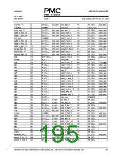
oaddr_2_ltxc_0
octrl_oen
46
47
48
49
IO_CELL
ENABLE
IO_CELL
IO_CELL
octrl_oen idat_13_ltxc_12
idat_14_ltxd_12
96
97
98
99
IN_CELL
IO_CELL
IN_CELL
IO_CELL
csd_oen
csd_oen
oaddr_3_ltxc_1
oaddr_4_lrxc_1
octrl_oen idat_15_ltxc_13
octrl_oen iprty_ltxd_13
NOTES:
1. When set high, HIZ_OEN forces all OUT_CELL and IO_CELL except
INTB and RSTOB to high impedance.
2. RX8K_OEN is the first bit of the boundary scan chain scanned in and out.
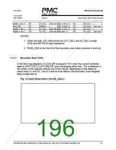
11.2.1
Boundary Scan Cells
In the following diagrams, CLOCK-DR is equal to TCK when the current controller
state is SHIFT-DR or CAPTURE-DR, and unchanging otherwise. The multiplexer in
the center of the diagram selects one of four inputs, depending on the status of
select lines G1 and G2. The ID Code bit is as listed in the Boundary Scan Register
table located above.
Fig. 12 Input Observation Cell (IN_CELL)
PROPRIETARY AND CONFIDENTIAL TO PMC-SIERRA, INC., AND FOR ITS CUSTOMERS’ INTERNAL USE
181

 PMC [ PMC-SIERRA, INC ]