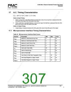
S/UNI-IMA-4 Telecom Standard Product Data Sheet
Released
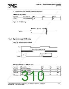
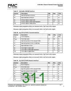
Table 47 Cell Buffer SDRAM Interface
Symbol
Ts
Description
Input Set-up time to SYSCLK
Min
2.5
Max
Units
ns
Th
Input Hold time to SYSCLK
0.3
ns
Tp
Tz
Tzb
SYSCLK High to Output Valid
SYSCLK High to Output High-Impedance
SYSCLK High to Output Driven
1
1
1
10.5
10
ns
ns
ns
Maximum output propagation delays are measured with a 20pF load on the outputs.
Minimum output propagation delays are measured with a 0 pF load on the outputs.
Table 48 Any-PHY/UTOPIA Transmit Interface
Symbol
Description
TCLK Frequency
Min
Max
52
Units
MHz
f
CLK
D
TCLK Duty Cycle
40
4
60
%
CLK
Ts
Ts
Th
Input Set-up time to TCLK (except TCSB)
ns
Input Set-up time to TCLK ( TCSB only)
Input Hold time to TCLK
6
1
ns
ns
Tp
Tz
Tzb
TCLK High to Output Valid
TCLK High to Output High-Impedance
TCLK High to Output Driven
1
1
1
12
12
ns
ns
ns
Maximum output propagation delays are measured with a 50pF load on the outputs.
Minimum output propagation delays are measured with a 0 pF load on the outputs.
Table 49 Any-PHY/UTOPIA Receive Interface
Symbol
Description
RCLK Frequency
Min
Max
52
Units
MHz
f
CLK
D
RCLK Duty Cycle
40
4
60
%
CLK
Ts
Ts
Th
Input Set-up time to RCLK (except RCSB)
ns
Input Set-up time to RCLK (RCSB)
Input Hold time to RCLK
6
1
ns
ns
Tp
Tz
Tzb
RCLK High to Output Valid
RCLK High to Output High-Impedance
RCLK High to Output Driven
1
1
0
12
12
ns
ns
ns
Proprietary and Confidential to PMC-Sierra, Inc., and for its customers’ internal use.
Document No.: PMC-2020889, Issue 2
311

 PMC [ PMC-SIERRA, INC ]