S/UNI-IMA-4 Telecom Standard Product Data Sheet
Released
17 A.C. Timing Characteristics
(TA = -40°C to +85°C, VDD = 3.3 V ± 8%)
Notes on Input Timing:
1. When a set-up time is specified between an input and a clock, the set-up time is measured from the
50% point of the input to the 50% point of the clock.
2. When a hold time is specified between a clock and an input, the hold time is measured from the 50%
point of the clock to the 50% point of the input.
Notes on Output Timing:
1. Output timing is measured between the 50% point of the clock to the 50% point of the output.
17.1 Microprocessor Interface Timing Characteristics
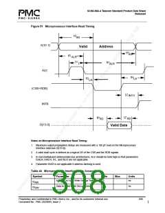
Table 43 Microprocessor Interface Read Access
Symbol
tS
Parameter
Address to Valid Read Set-up Time
Min
5
Max
Units
ns
AR
Address to Valid Read Hold Time
Address to Latch Set-up Time
Address to Latch Hold Time
5
ns
ns
ns
ns
ns
ns
ns
ns
ns
tH
AR
5
tS
ALR
5
tH
ALR
Valid Latch Pulse Width
20
0
tV
tS
L
Latch to Read Set-up
LR
Latch to Read Hold
5
tH
LR
Valid Read to Valid Data Propagation Delay
Valid Read Negated to Output Tristate
Valid Read Negated to Output Tristate
30
20
50
tP
RD
tZ
tZ
RD
INTH
Proprietary and Confidential to PMC-Sierra, Inc., and for its customers’ internal use.
Document No.: PMC-2020889, Issue 2
307

 PMC [ PMC-SIERRA, INC ]