RELEASED
PM73123 AAL1GATOR-8
DATASHEET
PMC-2000097
ISSUE 2
8 LINK CES/DBCES AAL1 SAR
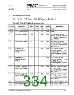
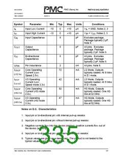
Symbol
Parameter
Min
-10
-10
Typ
0
Max
+10
+10
Units
µA
Conditions
I
I
Input Low Current
V = GND, Notes 2, 3
IL
IL
Input High Current
Input Capacitance
0
µA
V
= V , Notes 2, 3
IH DD
IH
C
C
C
5
pF
Excludes package.
Package typically 2 pF.
Note 5.
IN
Output
Capacitance
5
5
pF
pF
All pins. Excludes
package. Package
typically 2 pF. Note 5.
OUT
IO
Bi-directional
Capacitance
All pins. Excludes
package. Package
typically 2 pF. Note 5.
L
Pin Inductance
2
nH
All pins. Note 5.
PIN
I
Core Operating
Current (Low
Speed 2.5v).
72
mA
LS Mode, Outputs
typically loaded. All 8 links
in E1 mode.
DDOP
(LS2.5v)
IDDOP
I/O Operating
Current (Low
Speed mode 3.3v)
42
92
47
mA
mA
mA
LS Mode, Outputs
typically loaded. All 8 links
in E1 mode.
(
)
LS3.3v
I
Core Operating
Current (HS mode
2.5v).
HS Mode, Outputs
typically loaded. One HS
line at 52 MHz.
DDOP
(HS2.5v)
I
I/O Operating
Current (HS mode
3.3v).
HS Mode, Outputs
typically loaded. One HS
line at 52 MHz.
DDOP
(HS3.3v)
Notes on D.C. Characteristics:
1. Input pin or bi-directional pin with internal pull-up resistor.
2. Input pin or bi-directional pin without internal pull-up resistor.
3. Negative currents flow into the device (sinking), positive currents flow out of
the device (sourcing).
4. Input pin or bi-directional pin with internal pull-down resistor.
5. Typical values are given as a design aid. The product is not tested to the
typical values given in the data sheet.
PMC-SIERRA, INC. PROPRIETARY AND CONFIDENTIAL
335

 PMC [ PMC-SIERRA, INC ]