PM6341 E1XC
DATA SHEET
PMC-910419
ISSUE 8
E1 FRAMER/TRANSCEIVER
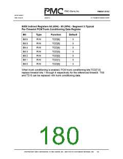
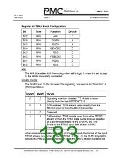
signalling data nibble in the lower four bits of the time slot byte. A logic 0 in
the DLEN bit position is reserved and should not be used.
GENCRC:
The GENCRC bit enables generation of the CRC multiframe when set to logic
1. When enabled, the TRAN generates the CRC multiframe alignment signal,
calculates and inserts the CRC bits, and if enabled by FEBEDIS, inserts the
FEBE indication in the spare bit positions. The CRC bits transmitted during
the first sub-multiframe (SMF) are indeterminate and should be ignored. The
CRC bits calculated during the transmission of the 'n'th SMF (SMF n) are
transmitted in the following SMF (SMF n+1). When GENCRC is set to logic 0,
the CRC generation is disabled. The CRC bits are then set to the logic value
contained in the Si[1] bit position in the International/National Bit Control
Register and bit 1 of the NFAS frames are set to the value of Si[0] bit if
enabled by INDIS, or, if not enabled by INDIS, are taken directly from
BTPCM. When BTPCM or Si[1] are transmitted in lieu of the calculated CRC
bits, there is no delay of one SMF (i.e., the BTPCM bits received in SMF n are
transmitted in the same SMF). The same applies when substituting Si[1] in
place of the calculated CRC bits.
FDIS:
The FDIS bit value controls the generation of the framing alignment signal. A
logic 1 in the FDIS bit position disables the generation of the framing pattern
in TS0 and allows the incoming data on BTPCM to pass through the TRAN
transparently. A logic 0 in FDIS enables the generation of the framing
pattern, replacing TS0 of frames 0,2,4,6,8,10,12,14 with the frame alignment
signal, and if enabled by INDIS, replacing TS0 of frames 1,3,5,7,9,11,13,15
with the contents of the International/National Bits Control Register. When
FDIS is a logic 1, framing is globally disabled and the values in controls bits
GENCRC, FEBEDIS, INDIS, and XDIS are ignored.
Note that the above is true only if the AIS bit in the Transmit Alarm /
Diagnostic Control Register is a logic 0. If AIS is logic 1, the output bit stream
becomes all ones unconditionally.
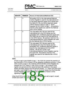
INDIS, GENCRC and FEBEDIS:
The INDIS bit controls the insertion of the International and National bits into
TS0. When INDIS is set to logic 0, the contents of the International/National
Bit Control Register are inserted into TS0; when INDIS is a logic 1, the
contents of the International/National Bit Control Register are ignored and the
values for those bit positions in the output stream are taken directly from the
BTPCM stream. When INDIS and FDIS are logic 0, the bit values used for
the International and National bits are dependent upon the values of the
GENCRC and FEBEDIS configuration bits, as follows:
PROPRIETARY AND CONFIDENTIAL TO PMC-SIERRA, INC., AND FOR ITS CUSTOMERS’ INTERNAL USE
168

 PMC [ PMC-SIERRA, INC ]