PMC-Sierra, Inc.
PRELIMINARY
PM5381 S/UNI-2488
DATASHEET
PMC-2000489
ISSUE 1
SATURN USER NETWORK INTERFACE FOR 2488 MBIT/S
13
FUNCTIONAL TIMING
13.1 Serial Line Interface
TBD
13.2 ATM Utopia Level 3 System Interface
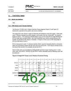
The Receive UTOPIA Level 3 System Interface Timing diagrams Figure 22 and Figure 23
illustrate the operation of the system side receive interface.
The single PHY case shown in Figure 22 illustrates the behaviour of the RCA signal. At the start
cycle 3, RENB is sampled low which initiates a cell transfer from the S/UNI-2488. The transfer
begins at cycle 4. The response to RENB always occurs on the rising RFCLK edge following the
RFCLK edge which samples RENB. Also note that RENB must remain asserted during a cell
transfer as specified by the Utopia L3 standard. In Figure 22, this occurs on the rising edge of
RFCLK at the start of cycle 9.
RCA is deasserted in cycle 11 coincident with the RSOC assertion indicating that the cell transfer
which has just started contains the last cell in the FIFO at this time. RCA may be asserted at any
time due to the insertion of a complete cell into the FIFO.
Back-to-back cells can be handled by holding RENB asserted at logic 0 during cycle 8. In this
case, cycle 10 for RSOC, RDAT[31:0], and RPRTY will be eliminated and the following cycles will
be advanced.
Figure 22 Single-PHY Utopia Level 3 Receive Functional Timing
1
2
3
4
5
6
7
8
9
10
11
12
RFCLK
RCA
RENB
RSOC
RDAT[31:0]
RPRTY
H1
P1
P10
P11
P12
H1
P1
Proprietary and Confidentail to PMC-Sierra Inc., and for its Customer’s Internal Use
441

 PMC [ PMC-SIERRA, INC ]