PMC-Sierra, Inc.
PRELIMINARY
PM5381 S/UNI-2488
DATASHEET
PMC-2000489
ISSUE 1
SATURN USER NETWORK INTERFACE FOR 2488 MBIT/S
G1:
The path status byte provides a path RDI function, and a path remote defect
indication function. Three bits are allocated for remote defect indications: bit 5
(the path RDI bit), bit 6 (the auxiliary path RDI bit) and bit 7 (Enhanced RDI
bit). Taken together these bits provide a eight state path RDI code that can be
used to categorize path defect indications.
In the transmit direction, the S/UNI-2488 provides register bits to control the
path RDI (bit 5) and auxiliary path RDI (bit 6) states. For path RDI, the number
of B3 errors detected in the previous interval is inserted either automatically or
using a register. This path RDI code has 9 legal values, namely 0 to 8 errors.
In the receive direction, a legal path RDI value is accumulated in the path RDI
event counter. In addition, the path RDI and auxiliary path RDI signal states
are available in internal registers.
H4:
The multi-frame indicator byte is a payload specific byte, and is not used for
ATM payloads. This byte is forced to 0x00 in the transmit direction, and is
ignored in the receive direction.
Z3 - Z5:
The path growth bytes provide three unused bytes for future use.
In the transmit direction, the growth bytes may be inserted from the three
THPP Path Growth byte registers.
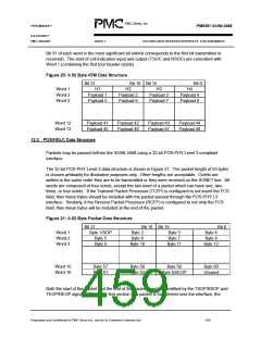
12.2.4 ATM Cell Data Structure
ATM cells may be passed to/from the S/UNI-2488 using a 52 byte cell structure on a 32-bit
UTOPIA level 3 compliant interface.
Figure 20 shows the default ATM cell format for the S/UNI-2488 at the UTOPIA Level 3 interface.
It is the 13x32-bit word structure with no HCS or UDF bytes.
Proprietary and Confidentail to PMC-Sierra Inc., and for its Customer’s Internal Use
437

 PMC [ PMC-SIERRA, INC ]