PMC-Sierra, Inc.
PRELIMINARY
PM5381 S/UNI-2488
DATASHEET
PMC-2000489
ISSUE 1
SATURN USER NETWORK INTERFACE FOR 2488 MBIT/S
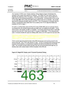
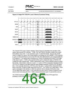
Figure 24 Single PHY POS-PHY Level 3 Receive Functional Timing
1
2
3
4
5
6
7
8
9
10
11
12
13
14
15
RFCLK
RENB
RSX
RSOP
REOP
RERR
RMOD[1:0]
RDAT[31:0]
RPRTY
RVAL
000 B1-B B5-B B9-B12
B41 B45
B52 B56 000 B2
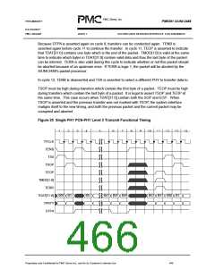
The Transmit POS Level 3 System Interface Timing (Figure 25) illustrates the operation of the
system side transmit FIFO interface. TENB, TSX, and TDAT[31:0] (which contains the in-band
PHY address since TSX = 1) are asserted in cycle 1 to start the transfer. Because the S/UNI-
2488 is a single-PHY device, the in-band address must always be set to 0x0000. DTPA responds
in cycle 3 to show that there is room in the FIFO (the FIFO fill threshold is user programmable) for
PHY address 0. The packet data is transferred on TDAT[31:0] starting at the rising TFCLK edge
at the start of cycle 3. TSOP is also asserted at this cycle to indicate the data on TDAT[31:24]
contains the start-of-packet byte. TENB is deasserted in cycle 3 by the upstream device to pause
the transfer. Data transfer continues in cycle 4. In cycle 6, DTPA is deasserted indicating that the
FIFO for PHY address 0 has fallen below the data available threshold (TXSDQ’s BT[7:0] register
bits). In the example shown here, BT[7:0] is set to the value 1 so that DTPA is deasserted when
there is less than 16 bytes of buffer space left in the FIFO. The TXSDQ FIFO status takes 1 clock
cycle to propagate to the interface so after the upstream device samples DTPA at the rising
TFCLK edge at the start of cycle 7, it can only write one more cycle of TDAT[31:0] before it must
stop to avoid overrunning the FIFO. TENB is deasserted before cycle 9 to prevent the overrun.
The TXSDQ hysteresis value (GHT[3:0] should be used to prevent the DTPA signal from
pulsating on and off while the FIFO is at the BA[7:0] threshold.
Proprietary and Confidentail to PMC-Sierra Inc., and for its Customer’s Internal Use
444

 PMC [ PMC-SIERRA, INC ]