S/UNI®-8x155 ASSP Telecom Standard Product Data Sheet
Released
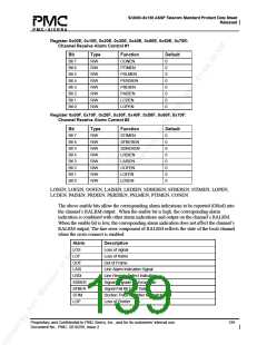
Register 0x010, 0x110, 0x210, 0x310, 0x410, 0x510, 0x610, 0x710:
RSOP Control/Interrupt Enable
Bit
Type
R/W
R/W
W
R/W
R/W
R/W
R/W
R/W
Function
BLKBIP
DDS
Default
Bit 7
Bit 6
Bit 5
Bit 4
Bit 3
Bit 2
Bit 1
Bit 0
0
0
X
0
0
0
0
0
FOOF
ALGO2
BIPEE
LOSE
LOFE
OOFE
OOFE:
The OOFE bit is an interrupt enable for the out-of-frame alarm. When OOFE is set to logic
one, an interrupt is generated when the out-of-frame alarm changes state.
LOFE:
The LOFE bit is an interrupt enable for the loss of frame alarm. When LOFE is set to logic
one, an interrupt is generated when the loss of frame alarm changes state.
LOSE:
The LOSE bit is an interrupt enable for the loss of signal alarm. When LOSE is set to logic
one, an interrupt is generated when the loss of signal alarm changes state.
BIPEE:
The BIPEE bit is an interrupt enable for the section BIP-8 errors. When BIPEE is set to
logic one, an interrupt is generated when a section BIP-8 error (B1) is detected.
ALGO2:
The ALGO2 bit position selects the framing algorithm used to determine and maintain the
frame alignment. When a logic one is written to the ALGO2 bit position, the framer is
enabled to use the second of the framing algorithms where only the first A1 framing byte
and the first 4 bits of the last A2 framing byte (12 bits total) are examined. This algorithm
examines only 12 bits of the framing pattern regardless; all other framing bits are ignored.
When a logic zero is written to the ALGO2 bit position, the framer is enabled to use the first
of the framing algorithms where all the A1 framing bytes and all the A2 framing bytes are
examined.
Proprietary and Confidential to PMC-Sierra, Inc., and for its customers’ internal use.
Document No.: PMC- 2010299, Issue 2
141

 PMC [ PMC-SIERRA, INC ]