S/UNI®-8x155 ASSP Telecom Standard Product Data Sheet
Released
Register 0x00E, 0x10E, 0x20E, 0x30E, 0x40E, 0x50E, 0x60E, 0x70E:
Channel Receive Alarm Control #1
Bit
Type
R/W
R/W
R/W
R/W
R/W
R/W
R/W
R/W
Function
CONEN
PTIMEN
PSLMEN
PERDIEN
PRDIEN
PAISEN
LCDEN
Default
Bit 7
Bit 6
Bit 5
Bit 4
Bit 3
Bit 2
Bit 1
Bit 0
0
0
0
0
0
0
0
0
LOPEN
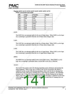
Register 0x00F, 0x10F, 0x20F, 0x30F, 0x40F, 0x50F, 0x60F, 0x70F:
Channel Receive Alarm Control #2
Bit
Type
R/W
R/W
R/W
R/W
R/W
R/W
R/W
R/W
Function
STIMEN
SFBEREN
SDBEREN
LRDIEN
LAISEN
OOFEN
LOFEN
LOSEN
Default
Bit 7
Bit 6
Bit 5
Bit 4
Bit 3
Bit 2
Bit 1
Bit 0
0
0
0
0
0
0
0
0
LOSEN, LOFEN, OOFEN, LAISEN, LRDIEN, SDBEREN, SFBEREN, STIMEN, LOPEN,
LCDEN, PAISEN, PRDIEN, PERDIEN, PSLMEN, PTIMEN, CONEN:
The above enable bits allow the corresponding alarm indications to be reported (ORed) into
the channel’s RALRM output. When the enable bit is high, the corresponding alarm
indication is combined with other alarm indications and output on the channel’s RALRM.
When the enable bit is low, the corresponding alarm indication does not affect the channel’s
RALRM output. The line error component of RALRM reflects the state of the local channel
when the cross-connect is enabled.
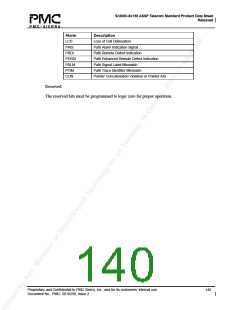
Alarm
LOS
Description
Loss of signal
LOF
Loss of frame
OOF
Out of Frame
LAIS
Line Alarm Indication Signal
Line Remote Defect Indication
Signal Degrade Bit Error Rate
Signal Fail Bit Error Rate
Section Trace Identifier Mismatch
Loss of Pointer
LRDI
SDBER
SFBER
STIM
LOP
Proprietary and Confidential to PMC-Sierra, Inc., and for its customers’ internal use.
Document No.: PMC- 2010299, Issue 2
139

 PMC [ PMC-SIERRA, INC ]