February, 2007
Station and Port Functions
4.1.2.1
Port Combinations
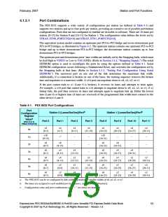
The PEX 8532 supports a wide variety of configurations per station (as defined in Table 4-1) and
supports two stations and up to four ports per station, providing an extensive set of possible port/station
configurations. Ports that are not configured or enabled are invisible to software. There are 16 lanes per
station, [0-15] for Station 0 and [16-31] for Station 1. The configuration value defines the levels set by
STRAP_STN0_PORTCFG[4:0] and STRAP_STN1_PORTCFG[4:0].
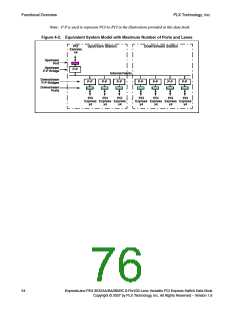
The equivalent system model contains an upstream port PCI-to-PCI bridge and seven downstream port
PCI-to-PCI bridges, as illustrated in Figure 4-2. The upstream station contains one upstream PCI-to-PCI
bridge and up to three downstream PCI-to-PCI bridges; the downstream station contains up to four
downstream PCI-to-PCI bridges.
The upstream port and downstream ports’ lane widths are initially set by the Strapping balls, which must
be tied High to VDD33 or Low to VSS (GND). (Refer to Section 3.4.4, “Strapping Signals.”) The serial
EEPROM option is used to reconfigure the ports by using the options defined in Table 4-1. Serial
EEPROM configuration occurs following a Fundamental Reset, and overrides the configuration set by
the Strapping balls at that time. (Refer to Section 5.3.3, “Setting Port Configuration Using Serial
EEPROM.”) The narrowest port on one end of the link determines the maximum link width.
Additionally, if a connection is broken on one of the lanes, the training sequence removes the broken
lane and negotiates to a narrower width. A x16 port can negotiate down to x8, x4, x2, or x1.
If the port cannot train to x1 (Lane 0 is broken), it reverses its lanes and attempts to train again.
For example, a x16 port that cannot train to x16 attempts to negotiate down to x8, x4, x2, or x1; if x1
linkup fails, the port then reverses its lanes and attempts again to negotiate link up. Either the lowest
lane (Lane 0) or highest lane (if lanes are reversed) of the programmed link width must connect to the
other device’s Lane 0.
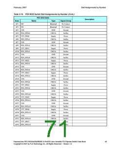
Table 4-1. PEX 8532 Port Configurations
Port
Station 0 [Lanes/SerDes]/Portb
Station 1 [Lanes/SerDes]/Portb
Configuration
Register
Valuea
Port 0
Port 1
Port 2
Port 3
Port 8
Port 9
Port 10
Port 11
(Port 0 or 8,
Offset 224h[4:0])
x4
[0-3]
x4
[4-7]
x4
[8-11]
x4
[12-15]
x4
[16-19]
x4
[20-23]
x4
[24-27]
x4
[28-31]
0h
1h
2h
3h
4h
5h
6h
x16
[0-15]
x16
[16-31]
c
–
–
–
–
–
–
–
–
–
–
–
–
x8
[0-7]
x8
[8-15]
x8
[16-23]
x8
[24-31]
x8
[0-7]
x4
[8-11]
x4
[12-15]
x8
[16-23]
x4
[24-27]
x4
[28-31]
x8
[0-7]
x4
[8-11]
x2
[12-13]
x2
[14-15]
x8
[16-23]
x4
[24-27]
x2
[28-29]
x2
[30-31]
x8
[0-7]
x2
[8-9]
x2
[10-11]
x4
[12-15]
x8
[16-23]
x2
[24-25]
x2
[26-27]
x4
[28-31]
x8
[0-7]
x2
[8-9]
x4
[10-13]
x2
[14-15]
x8
[16-23]
x2
[24-25]
x4
[26-29]
x2
[30-31]
a. The PEX 8532 can be re-configured by link-width negotiation to smaller widths of x8, x4, x2, or x1.
b. The lanes are assigned to each enabled port in sequence, as indicated in [brackets].
c. Configuration value and port combinations with “–” (no data) are reserved.
ExpressLane PEX 8532AA/BA/BB/BC 8-Port/32-Lane Versatile PCI Express Switch Data Book
Copyright © 2007 by PLX Technology, Inc. All Rights Reserved – Version 1.6
53

 PLX [ PLX TECHNOLOGY ]