February, 2007
Data Link Layer Considerations
8.4.5.3
DLLP UpdateFC Frequency Control
The INCH FC Update Pending Timer register (offset 9F4h) controls the amount of time a port can
wait before prioritizing an UpdateFC DLLP. Before the timer expires, TLPs have priority over
UpdateFC DLLPs. After the timer expires, UpdateFC DLLPs move to higher priority. The value
programmed into this CSR is a counter expiration value. All six VC&Ts in an ingress port share the
same counter upper limit; however, each has its own set of counters, for counting up.
The smaller the value written into these registers, the sooner an UpdateFC DLLP becomes higher
priority; therefore, the sooner the UpdateFC DLLP is transmitted. The sooner an UpdateFC is
transmitted, the less likely the chance to collapse two VC&T UpdateFCs. However, even for small timer
values, only one UpdateFC is typically sent per each incoming TLP. The UpdateFC is broken into
multiple DLLPs for each incoming TLP only if there are insufficient resources to replace the credit.
Note: Each VC and type has its own UpdateFC. Only UpdateFCs for the same VC&T can be collapsed.
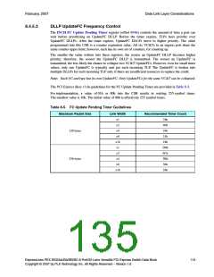
The PCI Express Base r1.0a guidelines for the FC Update Pending Timer are provided in Table 8-5.
For implementation, a value of 01h or 00h into the CSR results in waiting 255 symbol times.
The smallest value is 10h. The initial value of 00h is effectively 255 symbol times.
Table 8-5. FC Update Pending Timer Guidelines
Maximum Packet Size
Link Width
Recommended Timer Count
x1
x2
76h
40h
24h
21h
18h
D0h
6Ch
3Bh
36h
24h
128 bytes
x4
x8
x16
x1
x2
256 bytes
x4
x8
x16
ExpressLane PEX 8532AA/BA/BB/BC 8-Port/32-Lane Versatile PCI Express Switch Data Book
Copyright © 2007 by PLX Technology, Inc. All Rights Reserved – Version 1.6
113

 PLX [ PLX TECHNOLOGY ]