Philips Semiconductors
Preliminary specification
Stereo audio codec with SPDIF interface
UDA1355H
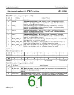
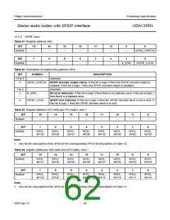
12.3.3 SPDIF INPUT
Table 81 Register address 59H
BIT
15
14
13
12
11
10
9
8
Symbol
−
−
−
−
−
−
−
SPDO_STATUS
BIT
7
6
5
4
3
2
1
0
Symbol
−
−
−
−
−
−
B_ERR
SPDIF_LOCK
Table 82 Description of register bits (address 59H)
BIT
SYMBOL
DESCRIPTION
15 to 9
8
−
reserved
SPDO_STATUS SPDIF encoder output status. If this bit is logic 0 then the SPDIF encoder output is
enabled; if this bit is logic 1 then the SPDIF encoder output is disabled.
7 to 2
1
−
reserved
B_ERR
Bit error detection. If this bit is logic 0 then there is no biphase error; if this bit is logic 1
then there is a biphase error.
0
SPDIF_LOCK
SPDIF lock indicator. If this bit is logic 0 then the SPDIF decoder block is not in lock; if
this bit is logic 1 then the SPDIF decoder block is in lock.
Table 83 Register address 5CH (left) and 5FH (right); note 1
BIT
Symbol
15
14
13
12
11
10
9
8
−
−
−
−
−
−
−
−
BIT
Symbol
7
6
5
4
3
2
1
0
SPDI_
BIT39
SPDI_
BIT38
SPDI_
BIT37
SPDI_
BIT36
SPDI_
BIT35
SPDI_
BIT34
SPDI_
BIT33
SPDI_
BIT32
Note
1. See for the description of the SPDI bit the corresponding SPDO bit description of Table 72.
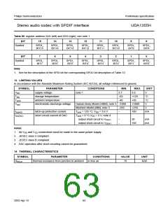
Table 84 register addresses 5BH (left) and 5EH (right); note 1
BIT
Symbol
15
14
13
12
11
10
9
8
SPDI_
BIT31
SPDI_
BIT30
SPDI_
BIT29
SPDI_
BIT28
SPDI_
BIT27
SPDI_
BIT26
SPDI_
BIT25
SPDI_
BIT24
BIT
Symbol
7
6
5
4
3
2
1
0
SPDI_
BIT23
SPDI_
BIT22
SPDI_
BIT21
SPDI_
BIT20
SPDI_
BIT19
SPDI_
BIT18
SPDI_
BIT17
SPDI_
BIT16
Note
1. See for the description of the SPDI bit the corresponding SPDO bit description of Table 72.
2003 Apr 10
62

 NXP [ NXP ]