Philips Semiconductors
Preliminary specification
Economy audio CODEC for MiniDisc (MD)
home stereo and portable applications
UDA1341TS
CONTENTS
7.21.1.10 Power control
7.21.2 DATA0 direct control
7.21.2.1 Volume control
7.21.2.2 Bass boost
7.21.2.3 Treble
7.21.2.4 Peak detection position
7.21.2.5 De-emphasis
7.21.2.6 Mute
1
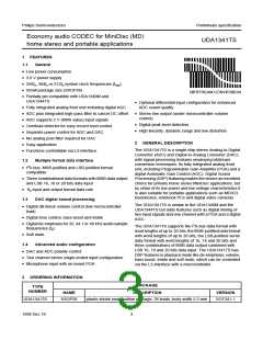
FEATURES
1.1
1.2
1.3
1.4
General
Multiple format data interface
DAC digital sound processing
Advanced audio configuration
2
3
4
5
6
7
GENERAL DESCRIPTION
ORDERING INFORMATION
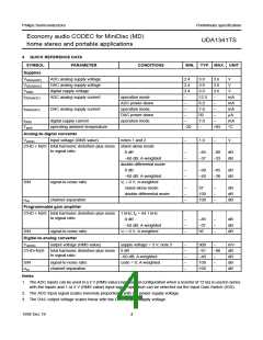
QUICK REFERENCE DATA
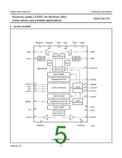
BLOCK DIAGRAM
7.21.2.7 Mode
7.21.3
DATA0 extended programming registers
7.21.3.1 Mixer gain control
7.21.3.2 MIC sensitivity
7.21.3.3 Mixer mode
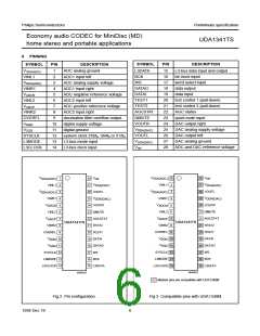
PINNING
7.21.3.4 AGC control
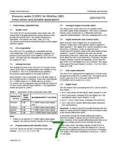
FUNCTIONAL DESCRIPTION
7.21.3.5 AGC output level
7.21.3.6 Input channel 2 amplifier gain
7.21.3.7 AGC time constant
7.1
System clock
7.2
Pin compatibility
7.3
Analog front end
7.21.4
DATA1 control
7.4
7.5
7.6
7.7
7.8
7.9
7.10
7.11
7.12
7.13
7.14
7.15
7.16
Programmable Gain Amplifier (PGA)
Analog-to-Digital Converter (ADC)
Digital Automatic Gain Control (AGC)
AGC status detection
Digital mixer
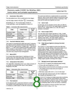
Decimation filter (ADC)
Overload detection (ADC)
Mute (ADC)
Interpolation filter (DAC)
Peak detector
Quick mute
Noise shaper (DAC)
Filter Stream Digital-to-Analog Converter
(FSDAC)
Multiple format input/output interface
L3-interface
7.21.4.1 Peak level value
8
LIMITING VALUES
9
THERMAL CHARACTERISTICS
DC CHARACTERISTICS
AC CHARACTERISTICS (ANALOG)
AC CHARACTERISTICS (DIGITAL)
APPLICATION INFORMATION
PACKAGE OUTLINE
10
11
12
13
14
15
SOLDERING
15.1
15.2
15.3
15.4
Introduction
Reflow soldering
Wave soldering
7.17
7.18
7.19
7.20
7.21
Repairing soldered joints
Address mode
Data transfer mode
Programming the sound processing and other
features
16
17
DEFINITIONS
LIFE SUPPORT APPLICATIONS
7.21.1
STATUS control
7.21.1.1 Reset
7.21.1.2 System clock frequency
7.21.1.3 DC-filter
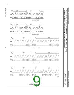
7.21.1.4 Data input format
7.21.1.5 Output gain switch
7.21.1.6 Input gain switch
7.21.1.7 Polarity of ADC
7.21.1.8 Polarity of DAC
7.21.1.9 Double speed
1998 Dec 18
2

 NXP [ NXP ]