Philips Semiconductors
Preliminary specification
Economy audio CODEC for MiniDisc (MD)
home stereo and portable applications
UDA1341TS
7
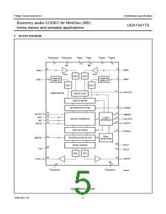
FUNCTIONAL DESCRIPTION
System clock
7.5
Analog-to-Digital Converter (ADC)
The stereo ADC of the UDA1341TS consists of two
3rd-order Sigma-Delta modulators. They have a modified
Ritchie-coder architecture in a differential switched
capacitor implementation. The over-sampling ratio is 128.
7.1
The UDA1341TS accommodates slave mode only, this
means that in all applications the system devices must
provide the system clock. The system frequency is
selectable. The options are 256fs, 384fs or 512fs.
The system clock must be locked in frequency to the digital
interface signals.
7.6
Digital Automatic Gain Control (AGC)
Input channel 2 has a digital AGC to compress the
dynamic range when a microphone signal is applied to
input channel 2. The digital AGC can be switched on and
off via the L3-interface. In the on state the AGC
compresses the dynamic range of the input signal of input
channel 2. Via the L3-interface the user can set the
parameters of the AGC: attack time, decay time and output
level. When the AGC is set off via the L3-interface, the gain
of input channel 2 can be set manually. In this case the
gain of the PGA and digital AGC are combined. The range
of the gain of the input channel 2 is from −3 to +60.5 dB in
steps of 0.5 dB.
7.2
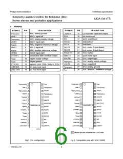
Pin compatibility
The UDA1341TS is partially pin compatible with the
UDA1340M and UDA1344TS, making an upgrade of a
printed-circuit board from UDA1340M to UDA1341TS
easier. The pins that are compatible with the UDA1340M
are marked in Fig.3.
7.3
Analog front end
The analog front end of the UDA1341TS consists of two
stereo ADCs with a Programmable Gain Amplifier (PGA)
in channel 2. The PGA is intended to pre-amplify a
microphone signal applied to the input channel 2.
7.7
AGC status detection
The AGCSTAT signal from the digital AGC is HIGH when
the gain level of the AGC is below 8 dB. This signal can be
used to give the PGA a new gain setting via the
L3-interface and to power e.g. a LED.
Input channel 1 has a selectable 0 or 6 dB gain stage, to
be controlled via the L3-interface. In this way, input signals
of 1 V (RMS value) or 2 V (RMS value) e.g. from a
CD source can be supported using an external resistor of
12 kΩ in series with the input channel 1. The application
modes are given in Table 1.
7.8
Digital mixer
The two stereo ADCs (including the AGC) can be used in
four modes:
Table 1 Application modes using input gain stage
• ADC1 only mode (for line input); input channel 2 is off
• ADC2 only mode, including PGA and digital AGC (for
microphone input); input channel 1 is off
INPUT
GAIN
SWITCH
RESISTOR
(12 kΩ)
MAXIMUM INPUT VOLTAGE
• ADC1 + ADC2 mixer mode, including PGA and AGC
Present
0 dB
2 V (RMS value) input signal;
note 1
• ADC1 and ADC2 double differential mode (improved
ADC performance).
Present
Absent
Absent
6 dB
0 dB
6 dB
1 V (RMS value) input signal
1 V (RMS value) input signal
0.5 V (RMS value) input signal
Important: In order to prevent crosstalk between the line
inputs no signal should be applied to the microphone input
in the double differential mode.
In all modes (except the double differential mode) a
reference voltage is always present at the input of the
ADC. However, in the double differential mode there is no
reference voltage present at the microphone input.
Note
1. If there is no need for 2 V (RMS value) input signal
support, the external resistor should not be used.
In the mixer mode, the output signals of both ADCs in
channel 1 and channel 2 (after the digital AGC) can be
mixed with coefficients that can be set via the L3-interface.
The range of the mixer coefficients is from 0 to −∞ dB in
1.5 dB steps.
7.4
Programmable Gain Amplifier (PGA)
The PGA can be set via the L3-interface at the gain
settings: −3, 0, 3, 9, 15, 21 or 27 dB.
1998 Dec 18
7

 NXP [ NXP ]