Philips Semiconductors
Preliminary specification
Economy audio CODEC for MiniDisc (MD)
home stereo and portable applications
UDA1341TS
The peak level detector is implemented as a peak-hold
detector, which means that the highest sound level is hold
until the peak level is read out via the L3-interface. After
read-out the peak level registers are reset.
7.9
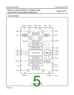
Decimation filter (ADC)
The decimation from 128fs is performed in two stages.
sin x
The first stage realizes 3rd order
characteristic,
-----------
x
decimating by 16. The second stage consists of
3 half-band filters, each decimating by a factor of 2.
7.14 Quick mute
A hard mute can be activated via the static pin QMUTE.
When QMUTE is set HIGH, the output signal is instantly
muted to zero. Setting QMUTE to LOW, the mute is
instantly in-activated.
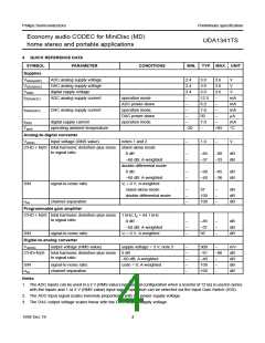
Table 2 Decimation filter characteristics
VALUE
(dB)
ITEM
CONDITIONS
0 to 0.45fs
7.15 Noise shaper (DAC)
Passband ripple
Stop band
±0.05
The 3rd-order noise shaper operates at 128fs. It shifts
in-band quantization noise to frequencies well above the
audio band. This noise shaping technique allows for high
signal-to-noise ratios. The noise shaper output is
converted into an analog signal using a filter stream
digital-to-analog converter.
>0.55fs
−60
Dynamic range
Overall gain
0 to 0.45fs
108
input channel 1;
0 dB input
−1.16
7.10 Overload detection (ADC)
7.16 Filter Stream Digital-to-Analog Converter
(FSDAC)
This name is convenient but a little inaccurate. In practice
the output is used to indicate whenever that output data, in
either the left or right channel, is bigger than −1 dB (actual
figure is −1.16 dB) of the maximum possible digital swing.
If this condition is detected the OVERFL output is forced
HIGH for at least 512fs cycles (11.6 ms at fs = 44.1 kHz).
This time-out is reset for each infringement.
The FSDAC is a semi-digital reconstruction filter that
converts the 1-bit data stream of the noise shaper to an
analog output voltage. The filter coefficients are
implemented as current sources and are summed at
virtual ground of the output operational amplifier. In this
way very high signal-to-noise performance and low clock
jitter sensitivity is achieved. A post filter is not needed due
to the inherent filter function of the DAC. On-board
amplifiers convert the FSDAC output current to an output
voltage signal capable of driving a line output.
7.11 Mute (ADC)
On recovery from power-down or switching on of the
system clock, the serial data output DATAO is held LOW
until valid data is available from the decimation filter.
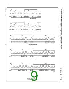
7.17 Multiple format input/output interface
7.12 Interpolation filter (DAC)
The UDA1341TS supports the following data formats:
• I2S-bus with word length up to 20 bits
The digital filter interpolates from 1fs to 128fs by means of
a cascade of a recursive filter and a Finite Impulse
Response (FIR) filter.
• MSB-justified serial format with word length up to 20 bits
• LSB-justified serial format with word length of
16, 18 or 20 bits
Table 3 Interpolation filter characteristics
VALUE
(dB)
• MSB data output with LSB 16, 18 or 20 bits input.
ITEM
CONDITIONS
0 to 0.45fs
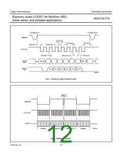
Left and right data-channel words are time multiplexed.
The formats are illustrated in Fig.4.
Passband ripple
Stop band
±0.03
>0.55fs
−50
The UDA1341TS allows for double speed data monitoring
purposes. In this case the sound features bass boost,
treble and de-emphasis cannot be used. However, volume
control and soft-mute can still be controlled. The double
speed monitoring option can be set via the L3-interface.
Dynamic range
0 to 0.45fs
108
7.13 Peak detector
In the playback path a peak level detector is build in.
The position of the peak detection can be set via the
L3-interface to either before or after the sound features.
The bit clock frequency must be 64 times word select
frequency or less, so fBCK ≤ 64 × fWS
.
1998 Dec 18
8

 NXP [ NXP ]