Philips Semiconductors
Product specification
New In Car Entertainment (NICE) car radio
TEA6845AH; TEA6845H
SYMBOL
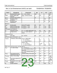
RR
PARAMETER
ripple rejection
CONDITIONS
MIN.
TYP.
40
MAX.
UNIT
dB
V
DDA1(ripple) = 100 mV (RMS);
−
−
fripple = 100 Hz
RDS update
Output: pin AFHOLD
Isink(max) maximum sink current
after first bus transmission
with AF = 1 (start of RDS
update); Vo = 0.5 V
1.0
1.0
1.2
1.2
1.4
1.4
mA
mA
Output: pin AFSAMPLE
Isink(max)
maximum sink current
no RDS update in progress;
Vo = 0.5 V
Test mode; note 3
Temperature compensation diode: pin DAATD
Vi(ext)
external input voltage to
clock state machine
VDAATD(L) = 2.5 V;
DAATD(H) = 3.5 V
2.5
0
−
−
6
3.5
5
V
V
V
V
Clock input: pin SCL
Vi(ext) external input voltage to
clock DAA
Time constant output: pin T1AMAGC
VSCL(L) = 0 V; VSCL(H) = 5 V
Vpulse
enabling voltage of load
PLL signal
pin fref in test mode
5.1
6.9
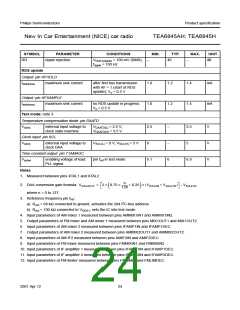
Notes
1. Measured between pins XTAL1 and XTAL2.
n
2. DAA conversion gain formula: VDAAOUT
=
2 × 0.75 ×
+ 0.25 × (VDAAIN + VDAATD) – VDAATD
---------
128
where n = 0 to 127.
3. Reference frequency pin fref:
a) Rext = 68 kΩ connected to ground, activates the 2nd I2C-bus address
b) Rext = 100 kΩ connected to VDDA1, sets the IC into test mode.
4. Input parameters of AM mixer 1 measured between pins AMMIX1IN1 and AMMIX1IN2.
5. Output parameters of FM mixer and AM mixer 1 measured between pins MIX1OUT1 and MIX1OUT2.
6. Input parameters of AM mixer 2 measured between pins IFAMP1IN and IFAMP1DEC.
7. Output parameters of AM mixer 2 measured between pins AMMIX2OUT1 and AMMIX2OUT2.
8. Input parameters of AM IF2 measured between pins AMIF2IN and AMIF2DEC.
9. Input parameters of FM mixer measured between pins FMMIXIN1 and FMMIXIN2.
10. Input parameters of IF amplifier 1 measured between pins IFAMP1IN and IFAMP1DEC.
11. Input parameters of IF amplifier 2 measured between pins IFAMP2IN and IFAMP2DEC.
12. Input parameters of FM limiter measured between pins FMLIMIN and FMLIMDEC.
2001 Apr 12
24

 NXP [ NXP ]