Philips Semiconductors
Product specification
New In Car Entertainment (NICE) car radio
TEA6845AH; TEA6845H
12 I2C-BUS PROTOCOL
12.1.3 I2C-bus pULL-UP RESISTORS
12.1 I2C-bus specification
When the IC is used together with the TEA6880H or
TEF6890H and both SCL and SDA lines are connected via
the I2C-bus to the TEA6880H or TEF6890H, the pull-up
resistors of the tuner IC should be connected to the digital
supply voltage of the TEA6880H or TEF6890H. Otherwise
an I2C-bus pull-down can occur switching off the tuner IC
supply when the I2C-bus buffer interface of the TEA6880H
or TEF6890H is enabled for data transfer to the tuner IC.
Information about the I2C-bus can be found in the brochure
“The I2C-bus and how to use it” (order number
9398 393 40011).
The standard I2C-bus specification is expanded by the
following definitions.
IC addresses:
• 1st IC address C2: 1100001
• 2nd IC address C0: 1100000.
12.1.4 FREQUENCY SETTING
For new frequency setting, in both AM and FM mode, the
programmable divider is enabled by setting bit MUTE =1.
To select an FM frequency, two I2C-bus transmissions are
necessary:
Structure of the I2C-bus logic: slave transceiver with auto
increment.
Subaddresses are not used.
12.1.1 TEST MODE
• First: bit MUTE = 1
• Second: bit MUTE = 0.
Connecting pin fref to VDDA1 via a 100 kΩ resistor or
feeding 50 µA into that pin switches the IC into the test
mode.
During test mode the digital-to-analog converters of the
level and antenna DAA functions can be sequenced by the
I2C-bus SCL line.
During test mode either the TEA6880H or TEF6890H
reference frequency, the PLL reference frequency divider
or the programmable divider output can be switched to
pin fref.
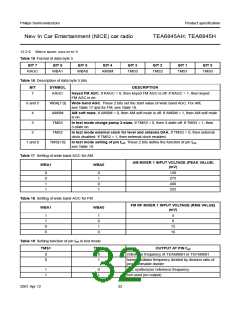
12.1.2 DATA TRANSFER FOR THE TEA6845
Data sequence: address, byte 1, byte 2, byte 3, byte 4,
byte 5, and byte 6. The data transfer has to be in this
order. The LSB = 0 indicates a WRITE operation to the
TEA6845.
Bit 7 of each byte is considered the MSB and has to be
transferred as the first bit of the byte.
The data becomes valid at the output of the internal
latches with the acknowledge of each byte. A STOP
condition after any byte can shorten transmission times.
When writing to the transceiver by using the STOP
condition before completion of the whole transfer:
• The remaining bytes will contain the old information
• If the transfer of a byte is not completed, this byte is lost
and the previous information is available.
In byte 5, 4 bits are reserved for test mode purposes.
Those can only be used when the test mode is activated
by the select pin fref.
2001 Apr 12
28

 NXP [ NXP ]