Philips Semiconductors
Product specification
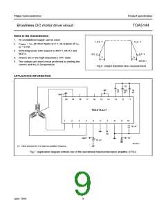
Brushless DC motor drive circuit
TDA5144
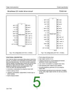
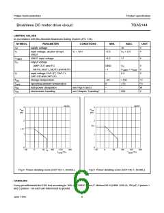
PINNING
PIN
SYMBOL
DESCRIPTION
SO20
SO28
MOT1
TEST
n.c.
1
2
1 and 2 driver output 1
3
4
test input/output
not connected
3
MOT2
n.c.
4
5 and 6 driver output 2
not connected
8 and 9 input voltage for the output driver stages
−
7
VMOT
GND3
FG
5
6
10
11
12
13
14
15
16
17
18
19
20
ground supply; must be connected
7
frequency generator: output of the rotation speed (open collector digital output)
ground supply return for control circuits
GND2
VP
8
9
supply voltage
CAP-CD
CAP-DC
CAP-ST
CAP-TI
+AMP IN
−AMP IN
AMP OUT
n.c.
10
11
12
13
14
15
16
−
external capacitor connection for adaptive communication delay timing
external capacitor connection for adaptive communication delay timing copy
external capacitor connection for start-up oscillator
external capacitor connection for timing
non-inverting input of the transconductance amplifier
inverting input of the transconductance amplifier
transconductance amplifier output (open collector)
21 and 22 not connected
23 and 24 driver output 3
MOT3
n.c.
17
18
19
20
25
26
not connected
MOT0
GND1
input from the star point of the motor coils
27 and 28 ground (0 V) motor supply return for output stages
June 1994
4

 NXP [ NXP ]