Philips Semiconductors
Product specification
CMOS single-chip 8-bit microcontrollers
80C31/80C51/87C51
EXPLANATION OF THE AC SYMBOLS
Each timing symbol has five characters. The first character is always
‘t’ (= time). The other characters, depending on their positions,
indicate the name of a signal or the logical status of that signal. The
designations are:
P – PSEN
Q – Output data
R – RD signal
t – Time
A – Address
V – Valid
C – Clock
W– WR signal
D – Input data
H – Logic level high
X – No longer a valid logic level
Z – Float
I – Instruction (program memory contents)
L – Logic level low, or ALE
Examples: t
= Time for address valid to ALE low.
= Time for ALE low to PSEN low.
AVLL
t
LLPL
t
LHLL
ALE
t
t
LLPL
AVLL
t
PLPH
t
LLIV
t
PLIV
PSEN
t
LLAX
t
PXIZ
t
PLAZ
t
PXIX
A0–A7
INSTR IN
A0–A7
PORT 0
PORT 2
t
AVIV
A0–A15
A8–A15
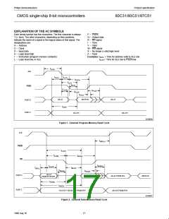
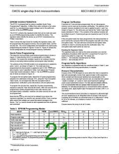
SU00006
Figure 1. External Program Memory Read Cycle
ALE
PSEN
RD
t
WHLH
t
LLDV
t
t
LLWL
RLRH
t
RHDZ
t
LLAX
t
t
RLDV
AVLL
t
RLAZ
t
RHDX
A0–A7
FROM RI OR DPL
PORT 0
PORT 2
DATA IN
A0–A7 FROM PCL
INSTR IN
t
AVWL
t
AVDV
P2.0–P2.7 OR A8–A15 FROM DPH
A0–A15 FROM PCH
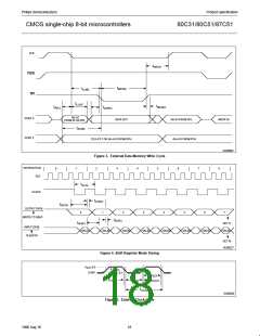
SU00007
Figure 2. External Data Memory Read Cycle
17
1996 Aug 16

 NXP [ NXP ]