Philips Semiconductors
Product specification
9-bit video input processor
SAA7113H
8
FUNCTIONAL DESCRIPTION
Analog input processing
8.2
Analog control circuits
The anti-alias filters are adapted to the line-locked clock
frequency via a filter control circuit. The characteristics are
shown in Fig.3. During the vertical blanking period, gain
and clamping control are frozen.
8.1
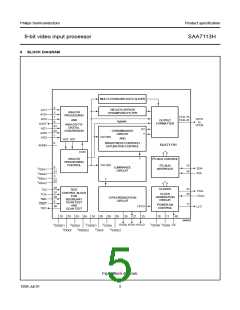
The SAA7113H offers four analog signal inputs, two
analog main channels with source switch, clamp circuit,
analog amplifier, anti-alias filter and video 9-bit CMOS
ADC; see Fig.6.
MGD138
6
handbook, full pagewidth
V
(dB)
0
−6
−12
−18
−24
−30
−36
−42
0
2
4
6
8
10
12
14
f (MHz)
Fig.3 Anti-alias filter.
amplitude, matched to the ADCs input voltage range.
The AGC active time is the sync bottom of the video signal.
8.2.1
CLAMPING
The clamp control circuit controls the correct clamping of
the analog input signals. The coupling capacitor is also
used to store and filter the clamping voltage. An internal
digital clamp comparator generates the information with
respect to clamp-up or clamp-down. The clamping levels
for the two ADC channels are fixed for luminance (120)
and chrominance (256). Clamping time in normal use is
set with the HCL pulse at the back porch of the video
signal.
Signal (white) peak control limits the gain at signal
overshoots. The flow charts (see Figs 7 and 8) show more
details of the AGC. The influence of supply voltage
variation within the specified range is automatically
eliminated by clamp and automatic gain control.
8.2.2
GAIN CONTROL
The gain control circuit receives (via the I2C-bus) the static
gain levels for the two analog amplifiers or controls one of
these amplifiers automatically via a built-in Automatic Gain
Control (AGC) as part of the Analog Input Control (AICO).
The AGC (automatic gain control for luminance) is used to
amplify a CVBS or Y signal to the required signal
1999 Jul 01
9

 NXP [ NXP ]