Philips Semiconductors
Product specification
Radio tuning PLL frequency synthesizer
SAA1057
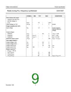
Notes
1. Pin 17 (XTAL) can also be used as input for an external clock.
The circuit for that is given in Fig.5. The values given in Fig.5 are a typical application example.
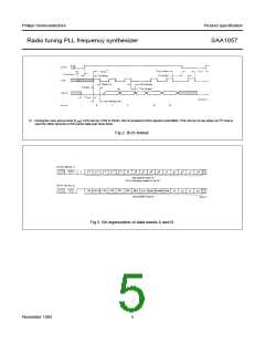
2. See BUS information in section ‘operation description’.
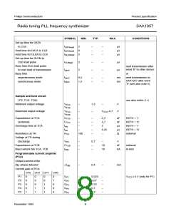
3. The output voltage at TCB and TCA is typically 1⁄2 VCC2+0,3 when the tuning system is in-lock via the sample and
hold phase detector. The control voltage at TCB is defined as the difference between the actual voltage at TCB and
the value calculated from the formula 1⁄2 VCC2+0,3 V.
4. Crystal oscillator frequency fXTAL = 4 MHz.
5. The busy-time after word “A” to another device which has more clock pulses than the SAA1057 (>17) must be the
same as the busy-time for a next transmission to the SAA1057.
When the other device has a separate DLEN or has less clock pulses than the SAA1057 it is not necessary to keep
to this busy-time, 5 µs will be sufficient.
6. When the bus is in the active mode (see BRM in Control Information), 4,5 mA should be added to the figures given.
7. Open collector output.
8. Measured in Fig.6.
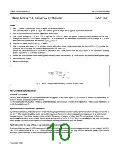
Fig.5 Circuit configuration showing external 4 MHz clock.
APPLICATION INFORMATION
Initialize procedure
Either a train of at least 10 clock pulses should be applied to the clock input (CLB) or word B should be transmitted, to
achieve proper initialization of the device.
For the complete initialization (defining all control bits) a transmission of word B should follow. This means that the IC is
ready to accept word A.
Synchronous/asynchronous operation
Synchronous loading of the frequency word into the programmable counter can be achieved when bit ‘SLA’ of word B is
set to ‘1’. This mode should be used for small frequency steps where low tuning noise is important (e.g. search and
manual tuning). This mode should not be used for frequency changes of more than 31 tuning steps. In this case
asynchronous loading is necessary. This is achieved by setting bit ‘SLA’ to ‘0’. The in-lock condition will then be reached
more quickly, because the frequency information is loaded immediately into the divider.
Restrictions to the use of the programmable current amplifier
The lowest current gain (0,023) must not be used in the in-lock condition when the supply voltage VCC2 is below 5 V (CP3,
CP2, CP1 and CP0 are all set to ‘0’). This is to avoid possible instability of the loop due to a too small range of the sample
and hold phase detector in this condition (see also section ‘Characteristics’).
November 1983
10

 NXP [ NXP ]