PCA9675
NXP Semiconductors
Remote 16-bit I/O expander for Fm+ I2C-bus with interrupt
7.2.2 Device ID (PCA9675 ID field)
The Device ID field is a 3-byte read-only (24 bits) word giving the following information:
• 8 bits with the manufacturer name, unique per manufacturer (for example,
NXP Semiconductors).
• 13 bits with the part identification, assigned by manufacturer, the 7 MSBs with the
category ID and the 6 LSBs with the feature ID (for example, PCA9675 16-bit
quasi-output I/O expander).
• 3 bits with the die revision, assigned by manufacturer (for example, Rev X).
The Device ID is read-only, hard wired in the device and can be accessed as follows:
1. START command
2. The master sends the Reserved Device ID I2C-bus address ‘1111 100’ with the R/W
bit set to 0 (write).
3. The master sends the I2C-bus slave address of the slave device it needs to identify.
The LSB is a ‘Don’t care’ value. Only one device must acknowledge this byte (the one
that has the I2C-bus slave address).
4. The master sends a Re-START command.
Remark: A STOP command followed by a START command will reset the slave state
machine and the Device ID read cannot be performed.
Remark: A STOP command or a Re-START command followed by an access to
another slave device will reset the slave state machine and the Device ID read cannot
be performed.
5. The master sends the Reserved Device ID I2C-bus address ‘1111 100’ with the R/W
bit set to 1 (read).
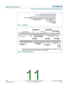
6. The device ID read can be done, starting with the 8 manufacturer bits (first byte +
4 MSB of the second byte), followed by the 13 part identification bits and then the 3
die revision bits (3 LSB of the third byte).
7. The master ends the reading sequence by NACKing the last byte, thus resetting the
slave device state machine and allowing the master to send the STOP command.
Remark: The reading of the Device ID can be stopped anytime by sending a NACK
command.
Remark: If the master continues to ACK the bytes after the third byte, the PCA9675
rolls back to the first byte and keeps sending the Device ID sequence until a NACK
has been detected.
For the PCA9675, the Device ID is as shown in Figure 11.
PCA9675
All information provided in this document is subject to legal disclaimers.
© NXP B.V. 2011. All rights reserved.
Product data sheet
Rev. 2 — 3 October 2011
10 of 34

 NXP [ NXP ]